Tidak ada produk di keranjang.
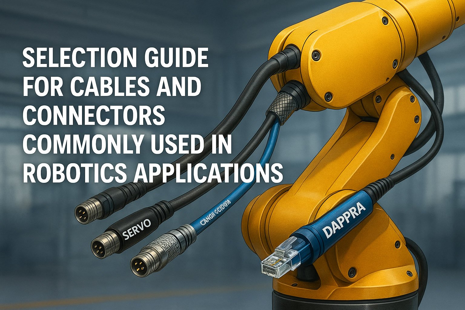
A Complete Guide to Cable & Connector Selection for Robotic Applications
Robotic systems live and die by the quality of their wiring. While algorithms, servo tuning, and motion control often get the spotlight, most field failures originate from something far more basic:
a fatigued cable, an improperly shielded feedback line, or a connector that was never designed for dynamic motion.
In high-speed robotic environments—multi-axis rotation, torsional loads, aggressive drag-chain movement—every cable and connector becomes a mechanical component. The purpose of this guide is to equip engineers with a complete, practical, and field-proven framework for selecting, installing, and maintaining robotic cables and connectors.
1. Robot Cable System Architecture
Robotic wiring must be understood not as individual cables—but as a functional system. Every cable type plays a mechanical and electrical role.
Power Cables
Used for servo motors, robot joints, and auxiliary actuators.
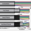
Key requirements: high current rating, insulation robustness, EMC immunity.
Signal Cables
Used for encoders, sensors, and I/O modules.
Key requirements: shielding quality, low capacitance, noise immunity.
Communication Cables
EtherCAT, Ethernet, CAN, RS485.
Key requirements: controlled impedance, twist consistency, paired shielding.
Hybrid Cables
Combine power + signal within a single structure.
Benefits: reduced cable bulk, simplified routing, improved EMC.
📌Robot Cable System Overview
Figure 1. High-level cable categories used in industrial robotic systems.
2. Mechanical Requirements (Movement, Torsion, Flex Cycles)
Robotic cables must survive millions of cycles of bending, twisting, vibration, and acceleration.
Bending Radius
- Typical: 7.5 × cable diameter
- Tighter bends reduce lifespan dramatically.
Torsional Angle
- ±180°/m for most industrial robots
- Up to ±360°/m for high-flex cobots
Flex-Life Rating
High-quality robot cables survive 5–15 million cycles.
Environmental Resistance
Different industries require different jackets:
| Environment | Recommended Jacket |
|---|---|
| Machining (oil) | PUR |
| Welding | Weld-spatter resistant |
| Metal edges | Abrasion-resistant |
| Outdoor | UV-resistant |
📌 Cable Types & Motion Ratings
Figure 2. Motion capabilities differ between drag-chain cables and torsion-rated robot cables.
3. Flex vs Torsion Zones on a 6-Axis Robot
Most cable failures occur because engineers route cables not according to joint movement type:
- J1–J3 → mostly bending
- J4–J6 → high torsion
- J6 wrist → highest dynamic stress
This determines what cable type must be used at each joint.
📌 Robot Cable Routing Zones
Figure 3. Flex and torsion zones on a 6-axis industrial robot, illustrating proper cable selection per joint movement type.
4. Connector Selection Factors
Connectors in robotic systems are mechanical components first and electrical components second.
They must withstand vibration, torsion, shock, coolant, oil mist, and continuous movement.
4.1 M8 / M12 Connectors
- A-coded: sensors & low-power I/O
- D-coded: 100 Mbps Ethernet
- X-coded: 1 Gbps high-speed industrial networks (EtherCAT, GigE)
4.2 Circular Power Connectors
Used for servo motors, brakes, and robot joints.
Key requirements:
- High current rating
- Robust locking
- Strong strain relief
- EMC shielding continuity
4.3 Hybrid Servo Connectors
Combine:
power + signal + feedback
→ Reduces cable bulk, improves EMC, simplifies robot-tail routing.
4.4 Locking Mechanisms
Choose based on environment:
| Type | Benefit |
|---|---|
| Threaded (M8/M12) | vibration-proof, industry standard |
| Bayonet | fast, secure locking |
| Push-pull | quick connect in tight spaces |
4.5 Ingress Protection
- IP65 – Dust + low-pressure water
- IP67 – Temporary immersion
- IP69K – High-pressure washdown environments
Robotic systems used in manufacturing typically require IP67 or better.
📌 Cable Selection Flowchart
Figure 4. A step-by-step decision flowchart for selecting the correct cable based on movement, environment, and shielding needs.
5. Failure Modes & Troubleshooting
Cable and connector failures often present as intermittent, hard-to-trace issues. The most common failure modes include:
5.1 Drag-Chain Wear & Jacket Cracking
Cause: Using non-dynamic cable in motion paths
Fix: Use PUR drag-chain or torsion-rated designs
5.2 Connector Pin Oxidation
Cause: moisture, vibration
Fix: sealed connectors, gold-plated pins
5.3 EMC-Induced Encoder Noise
Cause: insufficient shielding, parallel routing with servo power
Fix: double-shielded encoder cables, separate routing
5.4 Intermittent Signal Drops
Cause: torsion fatigue, micro-fractures
Fix: torsion-rated cable + proper strain relief
5.5 Pull-Out Failures
Cause: tight bend at connector entry
Fix: proper glands + grommets
📌 Common Cable Failure Modes
Figure 5. Typical robotic cable failure modes caused by bending, vibration, moisture, poor EMC, or inadequate strain relief.
6. Best Practices for Robotic Cable Routing
6.1 Separate Power & Signal Routes
Never run servo power and encoder lines in parallel.
6.2 Always Use Strain Relief
At connectors, junction boxes, and robot base plates.
6.3 Maintain Minimum Bend Radius
Follow manufacturer specs.
6.4 Avoid Sharp Edges
Use nylon bushings or protective sleeves.
6.5 Follow Robot-Tail Standards
KUKA, ABB, Fanuc all provide routing guides.
Following them prevents 90% of premature cable failures.
7. Practical Selection Framework
This section provides a field-ready framework used by robotic integrators and engineers at DAPPRA AUTOMATION.
7.1 Identify Application Type
Determine where the cable is installed:
- Drag-chain linear axis
- Torsional robot joints
- Static cabinet
- Hybrid mixed-motion zones
7.2 Select Cable According to Mechanical Stress
| Motion Type | Recommended Cable | Expected Life |
|---|---|---|
| Bending only | Drag-chain cable | 3–10 million cycles |
| Torsion motion | Robot torsion-rated cable | 5–15 million cycles |
| Static | Standard industrial cable | High |
7.3 Choose Shielding & Insulation
Match to noise environment:
- Servo motor noise → double shield
- Encoder sensitivity → foil + braid
- EtherCAT/Ethernet → controlled impedance 100 Ω
7.4 Select the Correct Connector Type
- Current rating
- Coding (A / D / X)
- Locking type
- IP protection level
- Strain relief compatibility
7.5 Installation & Routing Guidelines
- Strain relief mandatory
- Respect bending radius
- Separate noisy power cables
- Avoid unsupported spans
- Use proper clamps, glands, and sleeves
📌 Cable Selection Matrix
Figure 6. Cable selection matrix for determining the correct cable type based on motion profile and expected lifecycle.
8. Example Engineering Scenarios
Scenario: Recommended Cable Types for a 6-Axis Robot
- J1–J2: torsion-rated hybrid cable
- J3–J4: double-shielded encoder + power pair
- J5–J6: ultra-flex sensor cables
Connector Coding vs Protocol
| Coding | Protocol | Notes |
|---|---|---|
| A-coded | Sensors / I/O | Most common |
| D-coded | Ethernet | 100 Mbps |
| X-coded | EtherCAT / Gigabit | High EMI immunity |
Recommended Pairing
- PUR servo cable
- Double-shield encoder cable
- Hybrid servo connector with EMC shell
📌 Cable & Connector Mapping for a 6-Axis Robot
Figure 7. Mapping of cable and connector types across a 6-axis industrial robot, illustrating the recommended cable selection for each joint.
9. Engineering Checklists
These checklists are used internally at DAPPRA AUTOMATION for system validation.
✔ Robotic Cable Selection Checklist
- Rated for torsion or drag-chain motion
- PUR or TPE jacket
- Double shielding for feedback lines
- Fine-stranded conductors
- Correct voltage/current rating
- Oil/abrasion resistance
- Temperature rating
- Flex-life certification
- Impedance rating (for communication lines)
- Robot manufacturer compliance
✔ Connector Selection Checklist
- Correct coding (A/D/X)
- IP67 or better
- Proper strain relief
- Vibration-proof locking
- Pin plating (gold recommended)
- Shield continuity
- Temperature rating
- Matching cable diameter
✔ Routing Safety Checklist
- No tight bends
- Avoid sharp edges
- Separate power & signal
- Secure spans and clamp properly
- Leave slack for joint rotation
10. Summary
Selecting cables and connectors for robotic applications is not a minor task—it is core engineering work that determines uptime, safety, and system reliability. Mechanical motion, torsion load, shielding requirements, IP protection, and routing practices must all be considered as part of a unified design.
A robot is only as reliable as the weakest cable.
Invest properly in cabling, and your robot will reward you with uptime.
Related Articles
“Over 70% of robotic electrical failures originate not from components, but from improper cable routing and connector selection.”
— DAPPRA AUTOMATION Technical Engineering Team


Tambah komentar
Anda harus masuk untuk berkomentar.