
Tidak ada produk di keranjang.
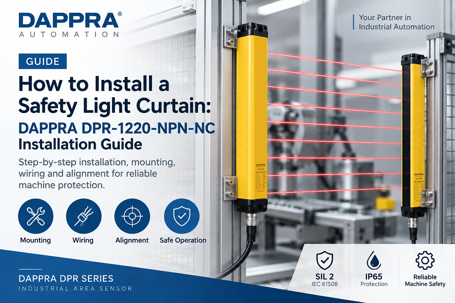
How to Install a Safety Light Curtain: DAPPRA DPR-1220-NPN-NC Installation Guide
Installation & Alignment Reference
DPR-1220-NPN-NC
Industrial Area Sensor & Safety Light Curtain · Installation Guide
This installation guide provides mounting, alignment and wiring reference information for the DAPPRA DPR-1220-NPN-NC Industrial Area Sensor and Safety Light Curtain. It is intended for engineers, technicians and maintenance personnel involved in machine integration and industrial automation installation.
Before You Install
Check the product package for the following items. For a complete list of contents and specifications, see the DPR-1220-NPN-NC product page.
- Transmitter — 1 unit
- Receiver — 1 unit
- Connection Cables — 2 cables
- Mounting Accessories — Brackets and mounting hardware
Operating Environment Check
| Parameter | Specification |
|---|---|
| Protection Rating | IP65 |
| Operating Temperature | -10°C to +55°C |
| Ambient Light Resistance | 10000 Lux |
| Power Supply | DC24V ±20% |
Required Tools
- Standard screwdriver set
- M4 or M5 hex key (depending on mounting brackets)
- Digital multimeter for wiring verification
- Adjustable wrench or spanner
- Spirit level for vertical alignment
- Cable ties or cable conduit (as required)
⚠ Safety Notice
Disconnect power before performing any electrical wiring. Installation should be carried out by qualified personnel in accordance with applicable local electrical codes and machine safety standards.
Mounting Methods
The DPR-1220-NPN-NC supports flexible installation according to different machine structures and protection requirements. The DPR Series supports three installation configurations: standard mounting, side mounting and adjustable mounting.
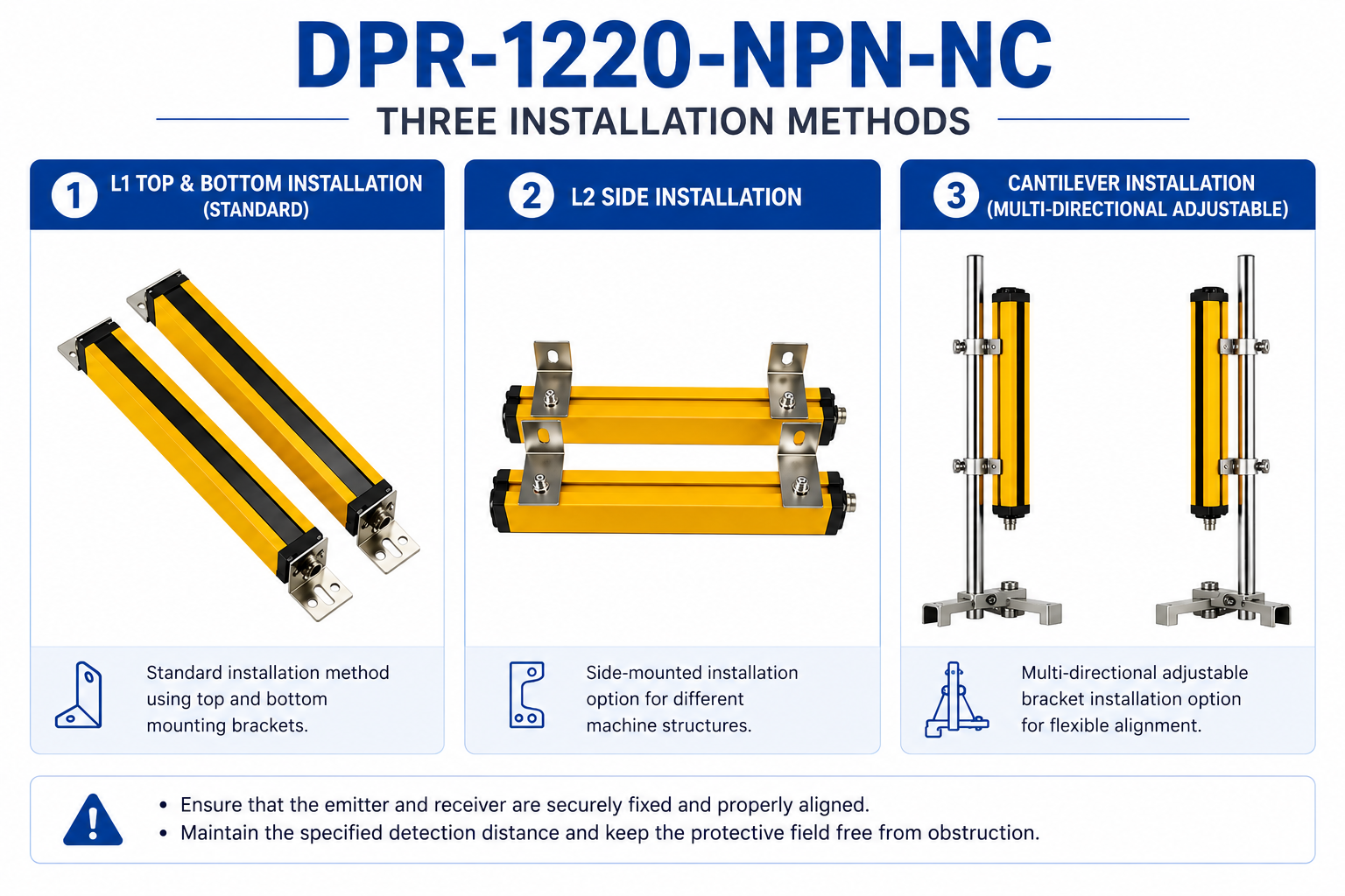
DPR-1220-NPN-NC installation options
1. Standard Vertical Installation
The transmitter and receiver are installed vertically opposite each other to create the required infrared detection field. This is the standard method for most machine protection and personnel protection applications.
2. Side Installation
Side installation can be considered when the machine structure limits the available mounting space. This method is suitable for compact equipment or customized machine layouts.
3. Adjustable Bracket Installation
Adjustable mounting brackets allow flexible positioning and alignment of the transmitter and receiver. This is useful for customized automation equipment where precise alignment is required.
Alignment Procedure
Proper alignment between the transmitter and receiver is essential for reliable detection performance. Follow the steps below to align the sensor correctly.
- Mount the transmitter and receiver — Install both units opposite each other at the required distance.
- Verify vertical alignment — Use a spirit level to ensure both units are vertically aligned.
- Check optical axis alignment — Position the transmitter and receiver so that the corresponding optical beams face each other directly.
- Power on the sensor — Apply DC24V power and observe the alignment indicators.
- Adjust position — Adjust the position or angle of the sensor units until proper alignment is achieved.
- Tighten mounting screws — After confirming alignment, tighten all mounting screws securely.
- Verify detection — Interrupt the beams with a test object and confirm the output signal changes correctly.
Alignment Tip
The DPR Series typically includes LED indicators on both transmitter and receiver to assist with alignment. Refer to the product datasheet or contact DAPPRA Automation for specific LED color codes and their meanings.
Wiring
The DPR-1220-NPN-NC uses an NPN NC output configuration. Before connecting the sensor to a PLC or controller, verify that the controller input circuit is compatible with the specified NPN output configuration.
Signal Output Condition
| Condition | Signal Output |
|---|---|
| Normal beam condition | 0V signal output |
| Beam interruption | No output |
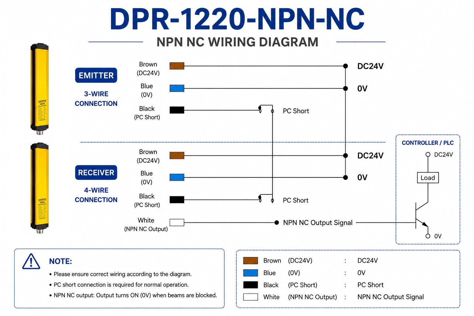
DPR-1220-NPN-NC NPN NC wiring diagram
Wiring Procedure
- Disconnect power — Ensure that the DC24V power supply is turned off before starting wiring.
- Connect power supply — Connect DC24V+ and 0V according to the wiring diagram.
- Connect output signal — Connect the NPN output to the appropriate PLC or controller input terminal.
- Check connections — Use a multimeter to verify continuity and correct polarity before applying power.
⚠ Wiring Notice
Incorrect wiring may damage the sensor or connected control equipment. Verify all connections carefully before applying power.
Function Verification
- Power-on check — Apply DC24V power and confirm that the sensor powers on normally.
- Alignment confirmation — Verify that the alignment indicators show proper alignment.
- Beam interruption test — Insert a test object into the detection area and confirm that the output changes.
- Output verification — Measure the output signal with a multimeter or verify the signal at the PLC input.
- Detection coverage test — Test detection at different positions within the 220 mm protection height.
- Environmental check — Confirm that ambient light, vibration and electromagnetic interference do not affect detection stability.
Maintenance
Regular maintenance helps ensure reliable long-term operation.
- Clean optical windows — Use a soft, lint-free cloth slightly moistened with isopropyl alcohol.
- Check mounting — Verify that mounting brackets remain secure.
- Check alignment — Periodically verify transmitter and receiver alignment.
- Inspect cables — Check for damage or loose connections.
- Verify detection — Test detection function periodically.
Maintenance Note
Do not disassemble the sensor housing. Internal components are not user-serviceable. For any internal issues, contact DAPPRA Automation technical support.
Troubleshooting
| Symptom | Possible Cause | Recommended Action |
|---|---|---|
| Sensor does not power on | Incorrect power supply or wiring | Verify DC24V supply and wiring polarity |
| Output does not change | Misalignment or blocked beam path | Check alignment and clear obstruction |
| Unstable detection | Vibration, ambient light or interference | Secure mounting; shield from direct light |
| Intermittent output | Loose wiring or connection | Check M12 connector and cable connections |
| Poor detection sensitivity | Dirty optical window | Clean optical windows with isopropyl alcohol |
| PLC does not respond | Input configuration mismatch | Verify PLC input is compatible with NPN output |
Frequently Asked Questions
How do I install and align a safety light curtain?
+
Install the transmitter and receiver vertically opposite each other with the correct detection distance. Use a spirit level to verify vertical alignment. Power on the sensor and observe the alignment indicators. Adjust the position or angle until proper alignment is confirmed, then tighten the mounting screws. Finally, interrupt the beams with a test object to verify detection.
How do I align the emitter and receiver of a light curtain?
+
Position the emitter and receiver directly opposite each other. Use a spirit level to ensure both units are at the same height and vertically aligned. Verify that the corresponding optical beams are facing each other. Most DPR Series sensors include LED alignment indicators to help confirm proper alignment.
Can a safety light curtain be connected to a PLC?
+
Yes. The NPN or PNP output can be connected to compatible PLC input circuits. Before installation, verify the PLC input specifications and wiring requirements to ensure compatibility with the sensor’s output configuration. The DPR-1220-NPN-NC uses NPN output with NC signal logic.
How do I connect an NPN safety light curtain to a PLC?
+
Connect the NPN output wire from the sensor to the PLC input terminal. Connect the PLC common terminal to the positive voltage (DC24V+). When the sensor output is active (0V), current flows from the PLC input through the sensor to ground. Verify the PLC input is configured for NPN (sinking) type.
What should I consider when installing a safety light curtain?
+
Consider proper alignment between the transmitter and receiver, stable mounting to prevent vibration-induced misalignment, adequate safety distance from the machine hazard, environmental conditions such as dust, oil, humidity and ambient light, and correct wiring to the control system.
What power supply does a safety light curtain require?
+
Most industrial safety light curtains and area sensors, including the DPR-1220-NPN-NC, operate with a DC24V ±20% power supply. Always verify the power supply specification before installation.
Can an NPN light curtain work with a PNP PLC input?
+
No, not directly. An NPN sensor output and a PNP PLC input have opposite polarity logic. To use an NPN sensor with a PNP PLC input, you need an interface relay, signal converter, or you should choose a PNP version of the sensor. The DPR Series offers both NPN and PNP versions.
DPR-1220-NPN-NC — Product Page
View full product specifications, pricing and ordering information.
Need Technical Support or a Quote?
Contact DAPPRA Automation for engineering assistance, pricing or OEM/ODM inquiries.
Contact DAPPRA Engineer









Tambah komentar
Anda harus masuk untuk berkomentar.