
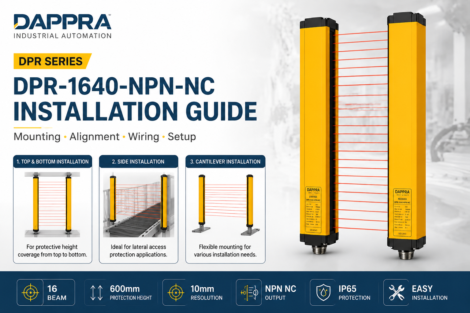
DAPPRA DPR-1640-NPN-NC Installation Guide | Mounting & Wiring Instructions
DPR-1640-NPN-NC
1. Safety Information
- Read this entire guide before beginning installation.
- Ensure the sensor is installed in accordance with all applicable local and national electrical codes.
- Do not operate the sensor outside the specified operating temperature range (-10°C to 55°C).
- Protect the sensor from excessive mechanical shock, vibration, and corrosive environments.
- Do not attempt to disassemble or modify the sensor housing.
- For safety applications, verify that the SIL 2 certification requirements are met in the final installation.
2. Product Overview
The DPR-1640-NPN-NC is a through-beam infrared area sensor consisting of a separate Emitter and Receiver. The emitter projects 16 parallel infrared beams across the detection area. When an object interrupts one or more beams, the receiver detects the interruption and changes the NPN NC output signal.
| Component | Function | Connector |
|---|---|---|
| Emitter | Generates 16 parallel infrared beams | M12, 3-pin |
| Receiver | Detects infrared beams and provides NPN NC output | M12, 4-pin |
3. Unpacking and Inspection
Carefully unpack the DPR-1640-NPN-NC and verify that all items are present and undamaged.
| Item | Qty | Description |
|---|---|---|
| Emitter | 1 | Infrared beam transmitter unit |
| Receiver | 1 | Infrared beam receiver unit |
| Connecting Cables | 2 | M12 connector cables, 2 m |
| Mounting Brackets (Top) | 2 | Top mounting brackets |
| Mounting Brackets (Bottom) | 2 | Bottom mounting brackets |
| Mounting Screws | 8 | M4 × 10 mm screws |
| Installation Guide | 1 | This document |
4. Installation Procedure
Step 1 — Determine Mounting Location
- Identify the mounting location based on the machine structure and protection requirements.
- Ensure sufficient clearance for the emitter and receiver (minimum 0.2 m, maximum 3 m apart).
- Ensure the mounting surface is flat, rigid, and free from excessive vibration.
- Allow access for cable connection and maintenance.
Step 2 — Select Installation Method
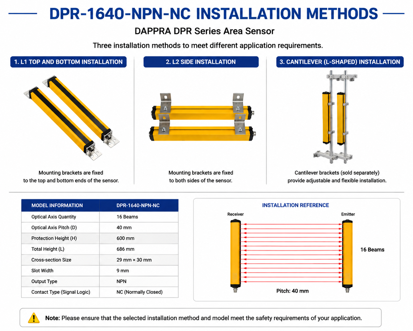
The DPR-1640-NPN-NC supports three installation methods. Select the appropriate method for your application.
| Method | Code | Description | Typical Application |
|---|---|---|---|
| Top & Bottom | L1 | Standard vertical mounting using top and bottom brackets | CNC, Press machines, Safety zones |
| Side Mount | L2 | Side-mounted option for restricted spaces | Compact equipment, Narrow spaces |
| Cantilever | L3 | Multi-directional adjustable bracket | Custom layouts, Robot cells |
Step 3 — Install Mounting Brackets
- Attach the top and bottom mounting brackets to the machine frame using appropriate screws (not supplied).
- For L1 (Top & Bottom): Mount brackets at the top and bottom of the detection area.
- For L2 (Side Mount): Mount brackets on the side of the machine frame.
- For L3 (Cantilever): Use adjustable brackets for multi-directional positioning.
- Ensure brackets are securely tightened and aligned vertically.
Step 4 — Mount Emitter and Receiver
- Secure the emitter to the bracket on one side of the detection area.
- Secure the receiver to the bracket on the opposite side.
- Ensure the emitter and receiver face each other directly.
- Both units must be at the same height and parallel to each other.
Step 5 — Optical Alignment
- Verify that the emitter and receiver are aligned within ±2° of each other.
- Check that all 16 beams are properly aligned across the detection area.
- Remove any obstructions from the detection zone.
- Use the LED indicators on the receiver to confirm beam alignment.
Step 6 — Tighten All Screws
- Secure all mounting hardware to the specified torque (recommended: 1.5–2.0 Nm for M4 screws).
- Do not overtighten, as this may damage the housing or brackets.
- Re-check alignment after tightening.
5. Wiring Connection
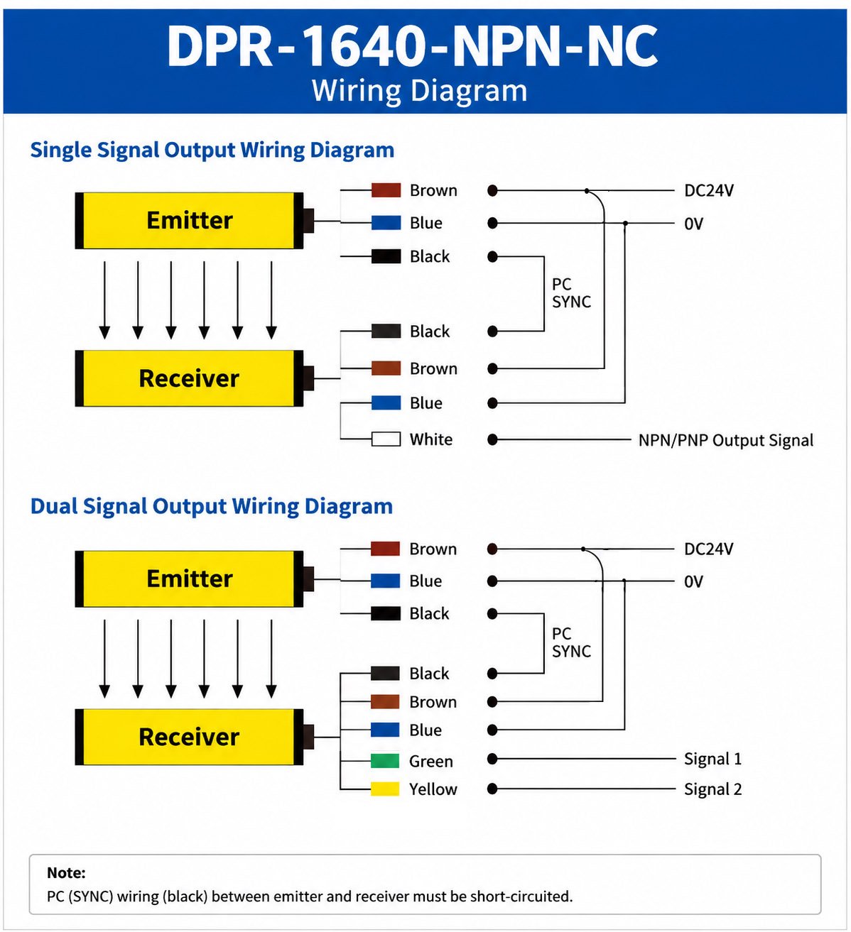
The DPR-1640-NPN-NC uses M12 4-pin connectors for both emitter and receiver. Use the supplied cables for connection.
| Wire Color | Pin | Function | Connection |
|---|---|---|---|
| Brown | 1 | Power Supply | DC24V+ (20.4–28.8V) |
| Blue | 3 | Ground | 0V |
| Black | 4 | NPN Output | Signal Output (NC) |
| White | 2 | Test Input | Optional test function (connect to 0V for test) |
6. Functional Testing
- Power on the sensor: Apply DC24V power to the emitter and receiver.
- Check LED indicators: The receiver LED should indicate normal beam condition.
- Test beam interruption: Pass an object through the detection area.
- Verify output signal: The NPN NC output should change state when beams are interrupted.
- Test all zones: Check that detection works across the entire protection height (600 mm).
7. Post-Installation Checklist
| ✅ | Check Item |
|---|---|
| ☐ | Emitter and receiver are securely mounted |
| ☐ | Emitter and receiver are vertically aligned and parallel |
| ☐ | All 16 beams are detected correctly |
| ☐ | Cables are properly connected and secured |
| ☐ | Power supply voltage is correct (DC24V ±20%) |
| ☐ | Beam interruption detected correctly across all zones |
| ☐ | Output signal responds correctly to beam interruption |
| ☐ | All screws are tightened to specification |
8. Technical Support
For technical support or installation assistance, reach out to DAPPRA Automation through any of the channels below.
Quickest response · Real-time support
🌐 Visit Websitedappra.com · Product resources & docs
✉️ Email Supportsupport@dappra.com · We respond within 24 hours