
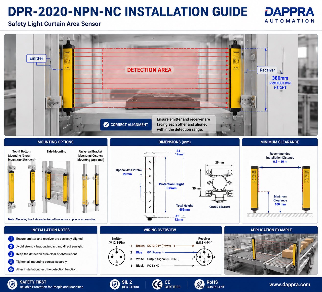
DPR-2020-NPN-NC Dimension & Installation Guide | Safety Light Curtain Setup
DPR-2020-NPN-NC
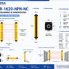
1. Dimension and Optical Structure
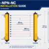
The DPR-2020-NPN-NC combines a compact mechanical design with a multi-beam infrared detection structure.
The sensor configuration includes:
- 20 optical beams
- 20 mm optical axis pitch
- 10 mm resolution
- 380 mm protection height
- 459 mm total height
- 29 × 30 mm housing cross-section
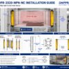
Dimension Drawing
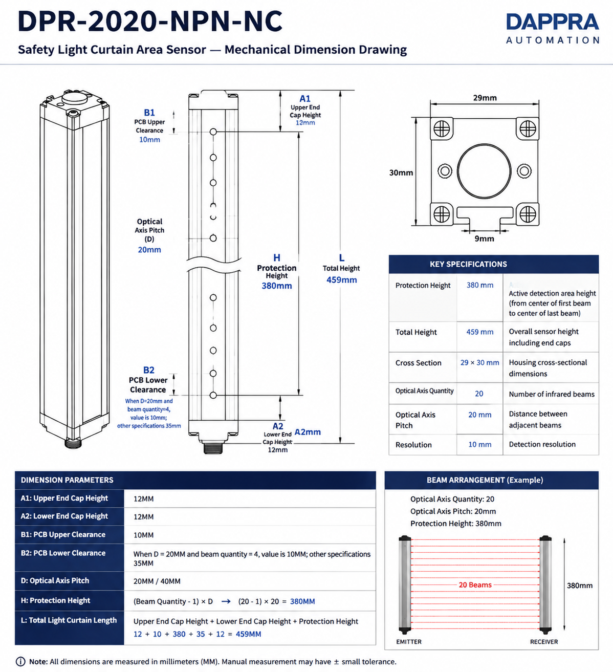
Mechanical Dimensions
| Dimension Parameter | Value (mm) |
|---|---|
| Protection Height | 380 |
| Total Height | 459 |
| Cross Section | 29 × 30 |
| Optical Axis Quantity | 20 |
| Optical Axis Pitch | 20 |
Protection Height Calculation
For DPR-2020-NPN-NC:
DPR-2020-NPN-NC — Safety Light Curtain Area Sensor
20 beams · 380 mm protection height · 20 mm pitch · NPN NC · IP65 · SIL 2
View Product →2. Installation Methods
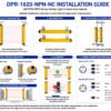
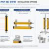
The DPR-2020-NPN-NC supports flexible installation methods to adapt to different industrial machine structures.
Installation options include:
- Top and bottom mounting
- Side mounting
- Cantilever installation
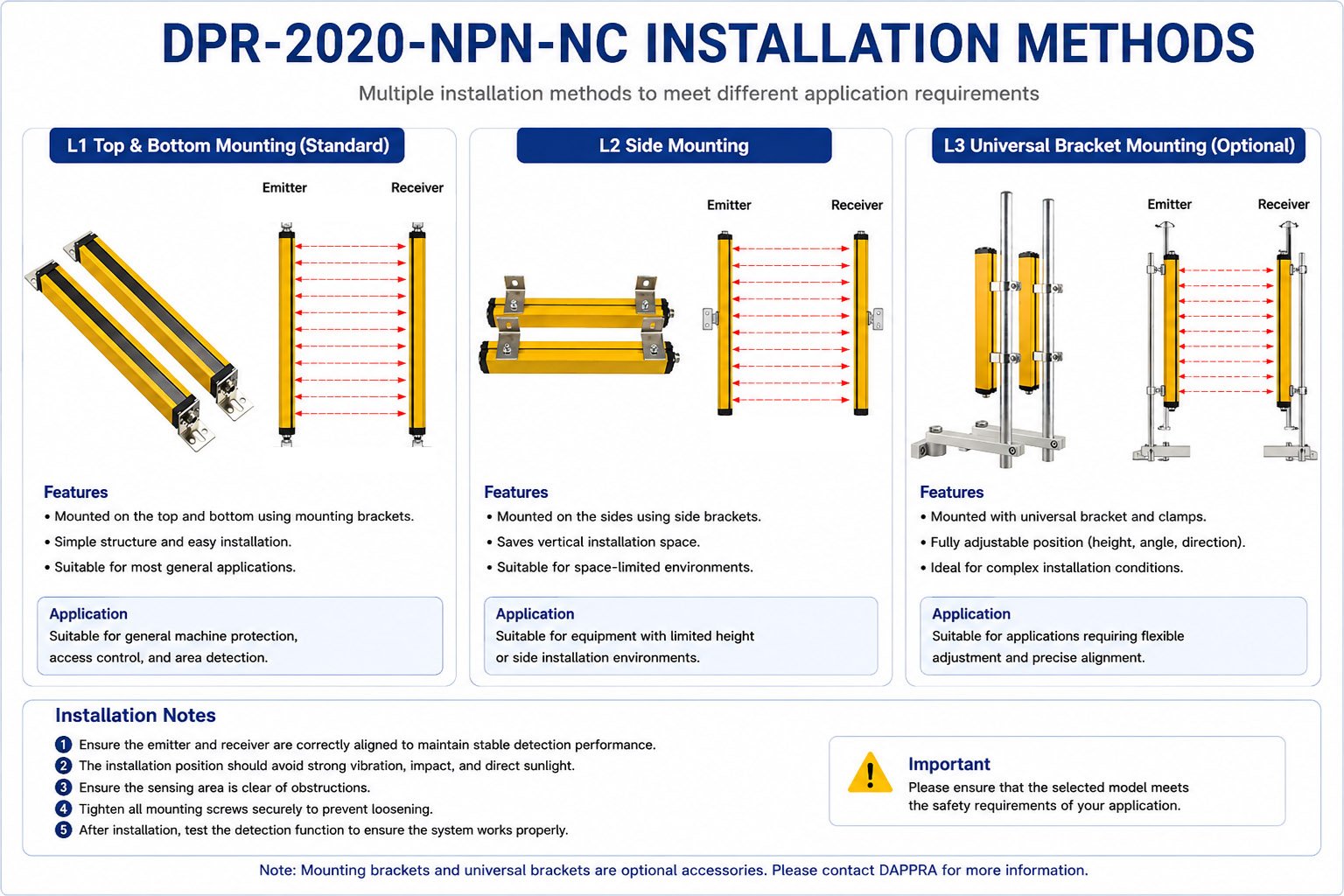
2.1 Installation Method 1 — Top and Bottom Mounting
Mounting brackets are fixed to the top and bottom ends of the sensor.
Suitable for:
- Standard machine guarding
- Vertical protective areas
- Equipment access protection
2.2 Installation Method 2 — Side Mounting
Mounting brackets are fixed to both sides of the sensor.
Suitable for:
- Limited installation space
- Machine side protection
- Flexible mounting positions
2.3 Installation Method 3 — Cantilever Mounting
Cantilever brackets provide adjustable and flexible installation and are sold separately.
Suitable for:
- Customized machine layouts
- Extended protection areas
- Flexible sensor positioning
2.4 Emitter and Receiver Mounting
Emitter Mounting: Fix the emitter securely using the mounting brackets.
Receiver Mounting: Fix the receiver securely using the mounting brackets.
The emitter and receiver should be securely mounted and positioned facing each other.
2.5 Emitter and Receiver Alignment
The emitter and receiver must be correctly aligned so that all infrared beams are received by the receiver.
After mounting, verify that the complete detection area is aligned before connecting the sensor to the machine control system.
- All beams clear → Output ON
- Beam interrupted → Output OFF
3. Wiring Guide
The DPR-2020-NPN-NC uses an M12 3-pin connector for the emitter and an M12 4-pin connector for the receiver.
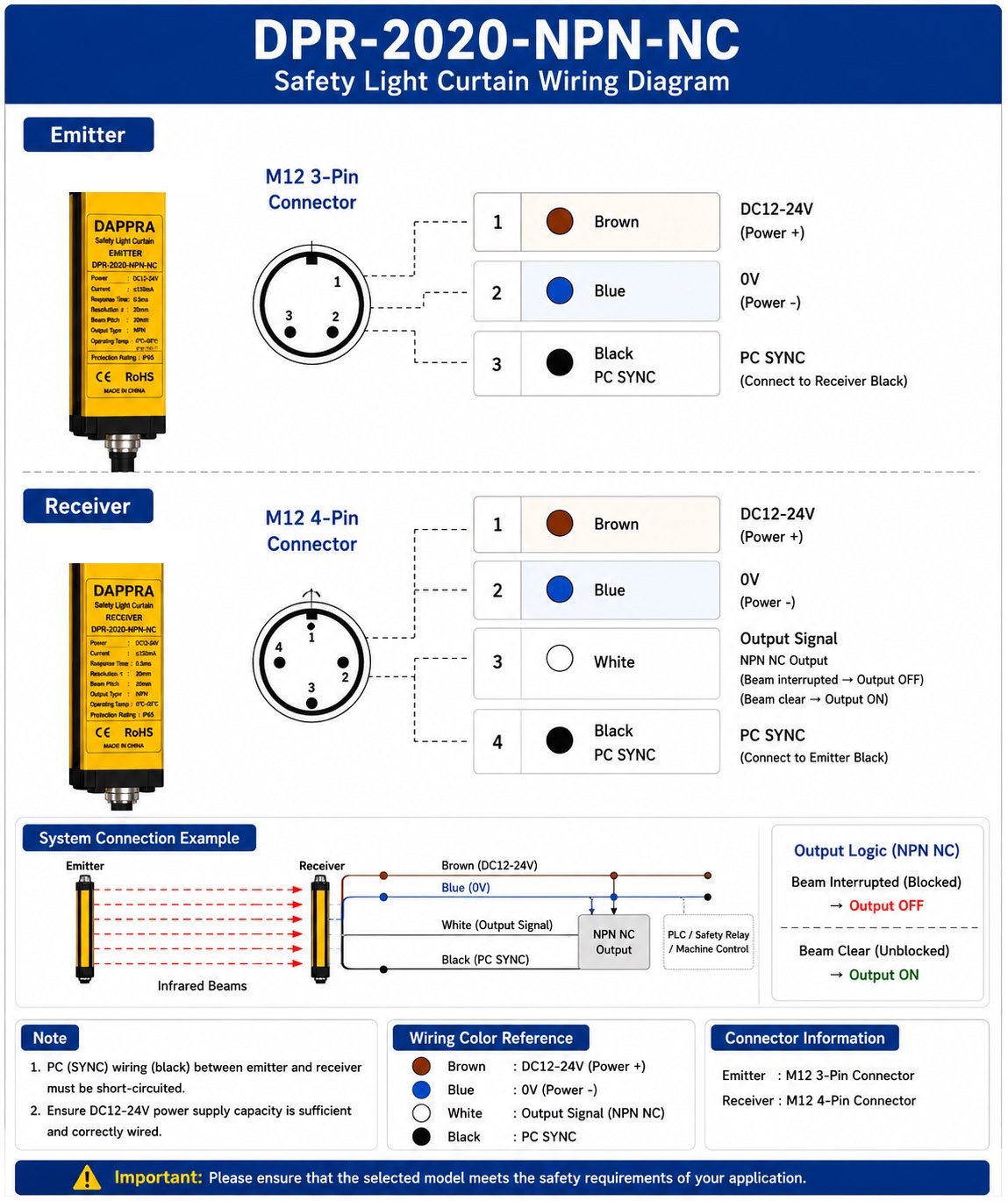
3.1 Emitter Wiring — M12 3-Pin
| Pin | Wire Color | Function |
|---|---|---|
| Pin 1 | Brown | DC24V |
| Pin 2 | Blue | 0V |
| Pin 3 | Black | PC SYNC |
3.2 Receiver Wiring — M12 4-Pin
| Pin | Wire Color | Function |
|---|---|---|
| Pin 1 | Brown | DC24V |
| Pin 2 | Blue | 0V |
| Pin 3 | White | NPN NC Output |
| Pin 4 | Black | PC SYNC |
3.3 PC SYNC Connection
Emitter Black → Receiver Black
The PC SYNC wiring between the emitter and receiver must be connected according to the wiring diagram.









Add comment
You must be logged in to post a comment.