
DPR-1240-PNP-NC Installation Diagram | Industrial Area Sensor Wiring & Mounting Guide
DAPPRA Automation
DPR-1240-PNP-NC
Industrial Area Sensor — Installation Diagram
🔧 DPR-1240-PNP-NC — Installation Guide
Three flexible mounting methods for easy integration into your machinery.
Vertical · Side · Adjustable bracket · 440 mm protection height
View Product →
1. Installation Overview
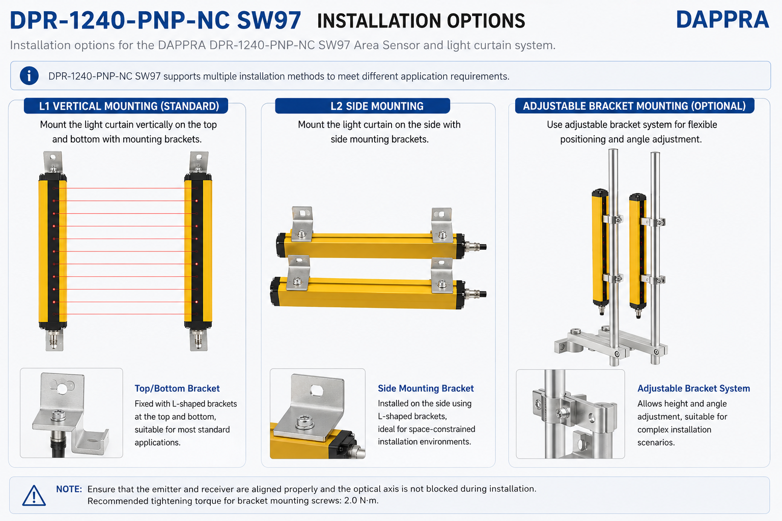
The DPR-1240-PNP-NC supports three installation methods. Select the appropriate method for your application.
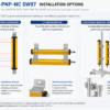
DPR-1240-PNP-NC — Three Installation Methods
⬆️⬇️
Top/Bottom Bracket
Fixed with L-shaped brackets at the top and bottom, suitable for most standard applications.
↔️
Side Mounting Bracket
Installed on the side using L-shaped brackets, ideal for space-constrained installation environments.
🔧
Adjustable Bracket System
Allows height and angle adjustment, suitable for complex installation scenarios.
Note: Ensure that the emitter and receiver are aligned properly and the optical axis is not blocked during installation.
⚠ Important: Recommended tightening torque for bracket mounting screws: 2.0 N·m. Do not overtighten as this may damage the housing or brackets.
📐 Flexible Installation · Reliable Protection
Choose the mounting method that best fits your machine structure.
All brackets and hardware included — ready to install
Shop Now →
2. Step-by-Step Installation Guide
Step 1 — Determine Mounting Location
- Identify the mounting location based on the machine structure and protection requirements.
- Ensure sufficient clearance for the emitter and receiver (minimum 0.2 m, maximum 3 m apart).
- Allow access for cable connection and maintenance.
Step 2 — Select Installation Method
- Top/Bottom Mounting: Use L-shaped brackets at the top and bottom of the detection area. Suitable for most standard applications.
- Side Mounting: Install brackets on the side of the machine frame. Ideal for compact equipment and restricted spaces.
- Adjustable Bracket: Use adjustable brackets for multi-directional positioning and alignment.
Step 3 — Mount Emitter and Receiver
- Secure the emitter to the bracket on one side of the detection area.
- Secure the receiver to the bracket on the opposite side.
- Ensure the emitter and receiver face each other directly and are vertically aligned.
- Both units must be at the same height and parallel to each other.
💡 Tip: Use a spirit level to ensure the brackets are perfectly vertical. Misalignment will affect detection reliability.
Step 4 — Optical Alignment
- Verify that the emitter and receiver are aligned within ±2° of each other.
- Check that all 12 beams are properly aligned across the detection area.
- Remove any obstructions from the detection zone.
- Use the LED indicators on the receiver to confirm beam alignment.
⚠ Important: Misalignment of the emitter and receiver will reduce detection distance and may cause false outputs. Align the units carefully before final tightening.
Step 5 — Tighten All Screws
- Secure all mounting hardware to the specified torque: 2.0 N·m.
- Do not overtighten, as this may damage the housing or brackets.
- Re-check alignment after tightening.
3. Wiring Connection
The DPR-1240-PNP-NC uses M12 4-pin connectors for both emitter and receiver. Use the supplied cables for connection.
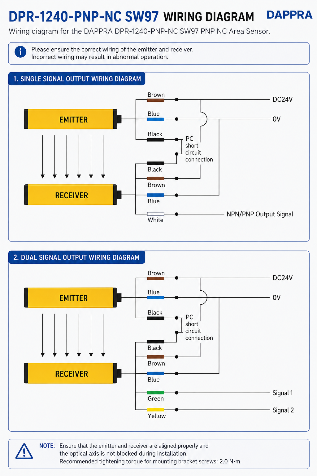
DPR-1240-PNP-NC — Wiring Diagram
| Wire Color | Pin | Function | Connection |
|---|---|---|---|
| Brown | 1 | Power Supply | DC24V+ (20.4–28.8V) |
| Blue | 3 | Ground | 0V |
| Black | 4 | PNP Output | Signal Output (NC) |
| White | 2 | Test Input | Optional test function |
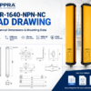
Note: For detailed electrical specifications, refer to the DPR-1240-PNP-NC Datasheet. For mechanical dimensions, refer to the CAD Drawing.
Available Resources: Datasheet PDF / CAD Drawing / Wiring Diagram / Installation Manual — Available from DAPPRA.
Available Resources: Datasheet PDF / CAD Drawing / Wiring Diagram / Installation Manual — Available from DAPPRA.
4. Post-Installation Checklist
| ✅ | Check Item |
|---|---|
| ☐ | Emitter and receiver are securely mounted |
| ☐ | Emitter and receiver are vertically aligned and parallel |
| ☐ | All 12 beams are detected correctly |
| ☐ | Cables are properly connected and secured |
| ☐ | Power supply voltage is correct (DC24V ±20%) |
| ☐ | Beam interruption detected correctly across all zones |
| ☐ | Output signal responds correctly to beam interruption |
| ☐ | All screws are tightened to 2.0 N·m |
Installation Guide
Version 1.0
SW97
🛒 DPR-1240-PNP-NC Industrial Area Sensor
12 beams · 440 mm protection height · PNP NC · IP65 · SIL 2
Reliable machine guarding and automation — order today
Learn More & Buy














Add comment
You must be logged in to post a comment.