Tidak ada produk di keranjang.
How to Build a PLC Remote Monitoring System: Complete Step-by-Step Guide
1. Introduction — Why Remote Monitoring Reduces Maintenance Cost
Remote monitoring is becoming an essential part of modern industrial automation.
Instead of sending engineers on-site for every issue, remote systems allow:
- Real-time production visibility
- Faster troubleshooting
- Lower travel and labor costs
- Predictive maintenance
- Centralized data management
A properly designed PLC remote monitoring system enables factories to operate smarter, safer, and more efficiently.
2. System Architecture — PLC → Gateway → Cloud
A PLC remote monitoring system typically includes three major layers:
2.1 PLC (Field Layer)
Handles:
- Machine control
- Real-time I/O
- Logic execution
- Local alarms
Data originates from PLC registers—status bits, counters, analog values, and error codes.
2.2 Industrial Gateway (Edge Layer)
The gateway performs:
- Reading PLC data (Modbus, S7, FINS, Ethernet/IP)
- Data filtering & buffering
- Protocol conversion (Modbus → MQTT / HTTPS)
- Local logic and preprocessing
- Store-and-forward during network loss
Gateways bridge the gap between closed industrial systems and cloud services.
2.3 Cloud Platform (Management Layer)
Cloud systems provide:
- Dashboards
- Alarms & notifications
- Data logs
- Historical trends
- Multi-site access
- Web and mobile visualization
Cloud platforms can be public (AWS IoT, Azure IoT) or private.
3. Signal & Data Path — Modbus → MQTT → API
A typical remote monitoring data chain:
Step 1: PLC exposes data through registers
Examples:
- Machine running status
- Cycle count
- Motor current
- Temperature
- Error codes
Step 2: Gateway reads data via Modbus
Supported variations:
- Modbus RTU
- Modbus TCP
The gateway periodically polls the PLC.
Step 3: Gateway publishes data via MQTT**
MQTT is lightweight, efficient, and designed for low-bandwidth environments.
Data is sent as:
- JSON payload
- Topic-based routing
- Retained or non-retained messages
Step 4: Cloud receives data through HTTP API or MQTT broker
The cloud uses:
- API endpoints
- Databases
- Visualization engines
Operators view machine data from anywhere.
4. Full Configuration Workflow
4.1 Configure PLC Communication Parameters
Set up:
- IP address
- Port number
- Modbus register map
- Data type (INT, DINT, REAL)
4.2 Configure Gateway Settings
Key parameters include:
- Server URL
- Client ID
- MQTT username/password
- Topic structure
- Upload interval
- Offline data buffer
Gateways must match PLC addressing exactly to prevent data errors.
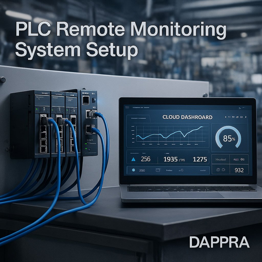
4.3 Build the Cloud Dashboard
A dashboard typically includes:
- Realtime values
- Device running status
- Alarm log
- Trend charts
- Productivity KPIs
Dashboards may provide mobile app access.
5. Engineering Use Case Examples
5.1 Water Pump Monitoring
Monitoring:
- Pressure
- Flow rate
- Motor current
- Start/stop frequency
Allows early detection of pump degradation.
5.2 CNC Machine OEE Data Collection
Collecting:
- Cycle time
- Idle time
- Alarm time
- Production count
Improves productivity analysis.
5.3 Temperature & Humidity Reporting
Sensors → PLC → Gateway → Cloud
Used for:
- Warehouses
- Food processing
- Electronics production
6. Common Problems in Remote Monitoring Projects
6.1 Internal Network Not Accessible
Firewalls or VLAN segmentation may block gateway access.
Solution:
- Use VPN / APN
- Configure port forwarding
- Whitelist cloud server IPs
6.2 MQTT Broker Connection Failure
Common issues:
- Wrong username/password
- Incorrect client ID
- Certificate mismatch
6.3 Data Packet Loss
Can be caused by:
- Weak cellular/WiFi signal
- Bandwidth saturation
- Gateway reboot
Store-and-forward prevents data loss.
7. Best Practices
✔ Use private VPN or APN
Improves security and reliability.
✔ Enable local data buffering
Ensures no data is lost during:
- Network loss
- Gateway reboot
- Server downtime
✔ Use encrypted communication
MQTT over TLS or HTTPS.
✔ Standardize topic naming
Consistent topic structure simplifies cloud processing.


Tambah komentar
Anda harus masuk untuk berkomentar.