Tidak ada produk di keranjang.

 Tanya dulu via WhatsApp
Overview
SDR-960-48 (ST91) Overview
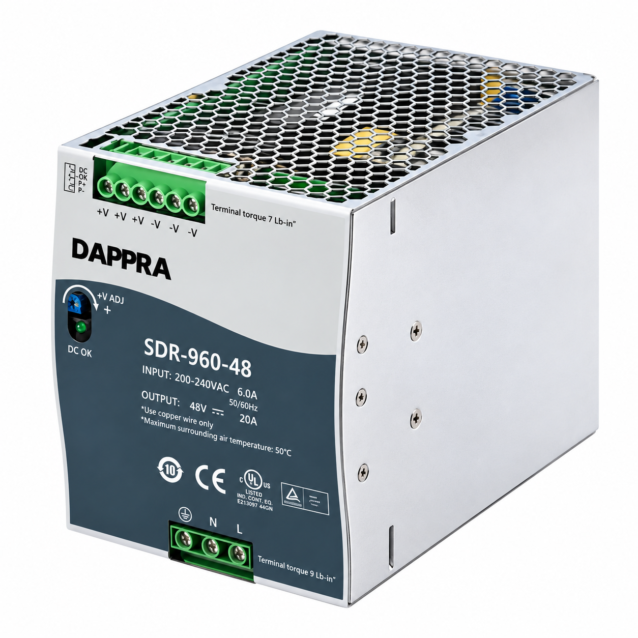
The DAPPRA SDR-960-48 (internal code ST91) is a 960W single-output DIN rail power supply delivering 48V DC at 20A. It belongs to the SDR Series 960W platform, which uses a 110 mm wide metal housing with free air convection cooling and mounts on TS35/7.5 or TS35/15 DIN rail.
The unit features built-in active PFC with power factor ≥ 0.95 at 230VAC full load, efficiency up to 94%, and 130% peak load capability for 3 seconds (peak current 26A) to support inductive and capacitive loads during startup. Protection includes short circuit, overload (constant current limiting with auto-recovery), over voltage and over temperature protection.
The SDR-960-48 provides a dedicated CN205 connector carrying P+/P− current-sharing signals and the DC OK relay contact, enabling parallel operation of up to 3+1 units for a maximum shared output of 3840W. This makes it suitable for 48V single-rail systems, N+1 redundant configurations and applications where a 48V bus is preferred for lower current, reduced cable loss or telecom-style loads.
Key Features
SDR-960-48 Key Features
A 960W DIN rail platform engineered for high-power, high peak-load and redundant 48V industrial applications.
- 960W Output · 48V / 20A48V DC at 20A (0–20A), 960W. +V ADJ 48–55V.
- 130% Peak Load for 3 SecondsUp to 1248W / peak current 26A for 3 seconds — supports inductive and capacitive startup loads.
- Built-in Active PFC (PF ≥ 0.95)Active power factor correction, compliant with BS EN/EN61000-3-2 harmonic current regulations.
- Efficiency up to 94%Reduces energy consumption and heat generation inside the control cabinet.
- Parallel Current Sharing — 3840W (3+1)P+ / P− via CN205; up to 3+1 units for a maximum shared output of 3840W.
- Dedicated CN205 Control ConnectorCurrent sharing and DC OK routed to a separate 4-pin connector, keeping TB2 output terminals uncluttered.
- Built-in DC OK Relay ContactCN205 pins 3,4 — remote status monitoring (Close = DC OK, Open = DC Fail).
- Complete Protection FunctionsShort circuit, overload (105–130% constant current limiting), over voltage and over temperature protection.
- SEMI F47 CompliantApproved for semiconductor fabrication equipment and installations requiring high immunity to voltage sags.
- TS35 DIN Rail · UL508 · 3-Year WarrantyTS35/7.5 or TS35/15 rail, 110 mm wide metal housing, UL508 approved.
Specifications
SDR-960-48 (ST91) Specifications
Output
| Model | SDR-960-48 (ST91) |
| DC Voltage | 48V |
| Rated Current | 20A |
| Current Range | 0–20A |
| Rated Power | 960W |
| Peak Current | 26A |
| Peak Power (3 sec.) | 1248W (130%) |
| Ripple & Noise | 250mVp-p |
| Adjustment | 48–55V |
| Tolerance | ±1.0% |
| Line / Load Reg. | ±0.5% / ±1.0% |
| Hold-up (typ.) | 14ms |
| Setup / Rise (typ.) | 1000ms / 100ms |
Protection
| Overload | 105–130% rated output, constant current limiting, 3 sec then shutdown; auto-recovery |
| Over Voltage | Shutdown with auto-recovery or re-power on to recover |
| Over Temperature | Shutdown, auto-recovery after temperature falls |
| Short Circuit | Auto-recovery |
Input
| Voltage | 180–264VAC · 254–370VDC |
| Frequency | 47–63Hz |
| AC Current (typ.) | 6A @ 230VAC |
| Inrush (typ.) | 50A @ 230VAC cold start |
| Power Factor | ≥ 0.95 @ 230VAC full load |
| Leakage | < 3.5mA @ 240VAC |
| Efficiency | 94% typ. @ 230VAC full load |
Functions
| DC OK Relay | 60VDC/0.3A · 30VDC/1A · 30VAC/0.5A |
| DC OK Indication | Front-panel LED |
| Voltage Adjustment | +V ADJ potentiometer |
| Current Sharing | P+ / P− via CN205; 3+1, max. 3840W |
| Parallel Operation | Supported |
Environment
| Working Temperature | −25 ~ +70°C (Derating above +50°C) |
| Storage Temperature | −40 ~ +85°C |
| Working Humidity | 20–90% RH non-condensing |
| Cooling | Free air convection (fanless) |
| Pollution Degree | 2 |
| Vibration | 10–500Hz, 2G, 10min/cycle, 60min each axis |
Safety & EMC
| Safety Standards | UL508, TUV BS EN/EN62368-1, AS/NZS 62368.1, EAC TP TC 004, BSMI CNS15598-1 |
| Withstand Voltage | I/P–O/P: 3kVAC |
| EMC Immunity | BS EN/EN61000-6-2 industrial immunity |
| Harmonic Current | BS EN/EN61000-3-2 compliant |
| Semiconductor | SEMI F47 approved |
Mechanical
| Dimensions (W×H×D) | 110 × 125.2 × 150 mm |
| Weight | Approx. 2.47 kg |
| Housing | Metal, slim design (110 mm width) |
| DIN Rail | TS35/7.5 or TS35/15 |
| Orientation | Vertical only (input at bottom) |
| Warranty | 3 Years |
Front Panel
| +V ADJ | Output voltage adjustment potentiometer (48–55V) |
| LED | DC OK indicator |
| FG | TB1 Pin 1 — must be connected to PE |
Notes
48V / 20A / 960W. Input restricted to 180–264VAC (not universal 88–264VAC). TB2: +V (1,2,3), −V (4,5,6). CN205: P− (1), P+ (2), DC OK (3,4). Ripple 250mVp-p. Efficiency 94%. Derating above +50°C.
Dimensions
SDR-960-48 Dimensions
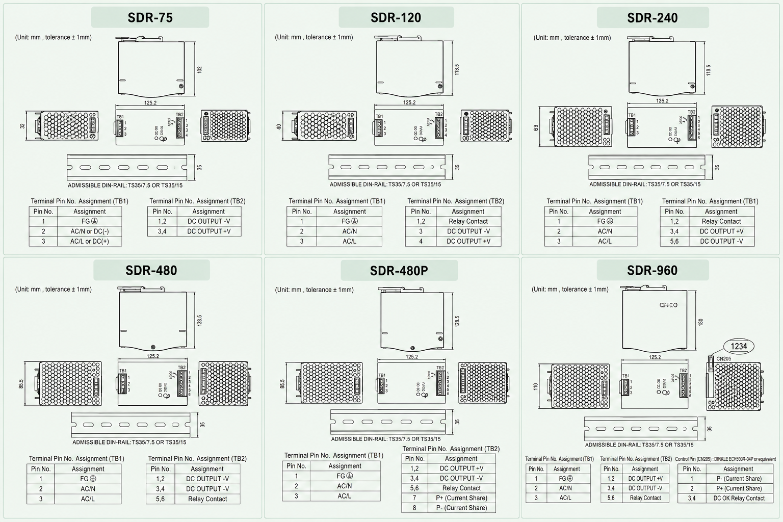
110 mm slim metal housing with a compact footprint for space-constrained control cabinets. All dimensions in mm, tolerance ±1 mm.
Mechanical
| Width (W) | 110 mm |
| Height (H) | 125.2 mm |
| Depth (D) | 150 mm |
| Weight | Approx. 2.47 kg |
| Housing | Metal, slim design |
Clearances
| Top/Bottom | 40 / 20 mm |
| Sides | 5 mm |
| DIN Rail | TS35/7.5 or 15 |
| Adjacent Heat Source | 15 mm (minimum) |
Installation
SDR-960-48 Installation
The SDR-960-48 requires vertical DIN rail mounting with specific ventilation clearance for reliable operation at 960W.
01 / 06
Vertical Orientation Only
Input terminals at the bottom, output at the top. Upside-down, horizontal or table-top mounting is not allowed.
02 / 06
Ventilation Clearance
5 mm sides, 40 mm top, 20 mm bottom. Keep 15 mm from adjacent heat sources.
03 / 06
TS35 Rail
TS35/7.5 or 15. Tilt, fit, slide, lock, check locking action.
04 / 06
FG to PE Required
TB1 Pin 1 (FG) must be connected to PE (Protective Earth) for safety and EMC.
05 / 06
Temperature & Derating
−25 to +70°C. Full load up to +50°C; derate above +50°C.
06 / 06
Pollution Degree 2
Dry, ventilated control cabinet. Do not install near water or high moisture.
High-Power Thermal Consideration
At 960W output the SDR-960-48 dissipates roughly 60W of heat at 94% efficiency. Ensure the cabinet has adequate airflow; if installed inside a sealed enclosure, an enclosure fan or heat exchanger is recommended.
Wiring
SDR-960-48 Wiring & Terminal
3-pin TB1 input, 6-pin TB2 output (three pins per polarity) and a separate 4-pin CN205 control connector.
TB1 — Input
| Pin | Assignment |
|---|---|
| 1 | FG (must connect to PE) |
| 2 | AC/N |
| 3 | AC/L |
TB2 — Output
| Pin | Assignment |
|---|---|
| 1, 2, 3 | DC OUTPUT +V |
| 4, 5, 6 | DC OUTPUT −V |
CN205 — Control
| Pin | Assignment |
|---|---|
| 1 | P− (current share) |
| 2 | P+ (current share) |
| 3, 4 | DC OK relay contact |
Wiring Specification
| Screw Torque (TB1/TB2) | 10 kgf-cm (9 Lb-in) |
| Wire Strapping | 5 mm (0.197") |
| Screwdriver | 3 mm or 4 mm slotted |
| Wire Type | Stranded copper only |
| CN205 Wire | 0.081–0.517 mm² (28–20 AWG) |
| CN205 Housing | DINKLE ESC250V-04P or equiv. |
All three +V pins and all three −V pins must be connected to their respective output wires to prevent excessive current stress on a single contact at 20A output. FG (Pin 1) must be connected to PE. Always verify the terminal label before wiring.
DC Output Voltage Adjustment
The SDR-960-48 includes a front-panel +V ADJ potentiometer with a 48–55V range and a DC OK indicator LED. Output current and wattage must not exceed the rated 20A / 960W.
Parallel Operation
Current Sharing up to 3840W (3+1)
The SDR-960-48 supports parallel operation for high-power or N+1 redundant systems using the CN205 current-share signals.
Up to 3+1 SDR-960-48 units can be connected in parallel for a maximum shared output of 3840W. Each unit contributes its share of the total load through the P+ / P− current-sharing bus carried on CN205 pins 1 and 2. In a 3+1 configuration, three units carry the load while the fourth provides N+1 redundancy, so the system continues to operate if one unit fails.
Parallel Configuration
| Configuration | 3+1 units |
| Units in Parallel | Up to 4 units |
| Max Shared Output | 3840W |
| Current Share Bus | CN205 pin 1 (P−) / pin 2 (P+) |
| Output Wiring | +V to +V, −V to −V |
Parallel Wiring Notes
| P+ / P− Connection | All units' P+ joined; all P− joined |
| Output Cables | Equal length and equal gauge |
| Output Voltage | Set each +V ADJ to the same value first |
| Redundancy | 3+1 provides N+1 redundancy |
When paralleling, set all units' output voltage to the same value using the +V ADJ potentiometer before connecting the current-share bus. Use equal-length, equal-gauge output cables to ensure balanced current distribution.
Safety
SDR-960-48 Safety & Cautions
- Qualified technician only. Do not remove the case yourself.
- Do not connect primary and secondary sides together — electric shock / arc hazard.
- Burn hazard. Do not touch the unit in operation and shortly after disconnection.
- Protect openings from foreign objects and dripping liquids.
- FG (TB1 Pin 1) must be connected to PE.
- Do not exceed 20A / 960W rated output.
- Disconnect the system from supply voltage before installation, maintenance or modification.
- Replace fuse only with same type and rating.
- Component for final equipment; final EMC must be re-confirmed.
Note: Pollution Degree 2 applies where only non-conductive pollution may temporarily become conductive due to occasional condensation — typically dry, well-ventilated control cabinets.
Applications
SDR-960-48 Industrial Applications
Industrial Control Systems
Semiconductor Fabrication
Factory Automation
Redundant Power Systems
Electrical Panels
Process Control
Test & Measurement
Machine Control
Telecom-Style 48V Loads
Next Step
Need the SDR-960-48 (ST91)?
Contact DAPPRA Automation — or explore the full SDR Series.
Support
SDR-960-48 FAQ
What is the SDR-960-48 (ST91)?
The SDR-960-48 (internal code ST91) is a 960W single-output DIN rail power supply delivering 48V DC at 20A. It is the 48V variant of the DAPPRA SDR Series 960W platform and includes built-in active PFC, 130% peak load capability for 3 seconds, DC OK relay contact and parallel current sharing up to 3840W (3+1).
What is the input voltage range of the SDR-960-48?
The SDR-960-48 supports 180–264VAC or 254–370VDC input only. It does not accept the universal 88–264VAC range offered by the SDR-75, SDR-120, SDR-240 and SDR-480 models.
What output voltage and current does the SDR-960-48 provide?
The SDR-960-48 provides 48V DC at 20A for a rated output of 960W, with a voltage adjustment range of 48–55V via the front-panel +V ADJ potentiometer.
What is the peak load capability of the SDR-960-48?
The SDR-960-48 delivers 130% peak load — up to 1248W with a peak current of 26A — for 3 seconds, to support inductive and capacitive loads during startup.
Does the SDR-960-48 support parallel current sharing?
Yes. The SDR-960-48 supports current sharing up to 3840W using a 3+1 configuration (up to 4 units in parallel). The P+ and P− current-share signals are carried on the CN205 connector, pins 2 and 1 respectively.
What is the efficiency of the SDR-960-48?
The SDR-960-48 achieves 94% typical efficiency at 230VAC full load, with power factor ≥ 0.95 and compliance with BS EN/EN61000-3-2 harmonic current regulations.
What is the terminal pin assignment of the SDR-960-48?
TB1 (input): Pin 1 = FG, Pin 2 = AC/N, Pin 3 = AC/L. TB2 (output): Pins 1, 2, 3 = DC OUTPUT +V; Pins 4, 5, 6 = DC OUTPUT −V. CN205 (control): Pin 1 = P−, Pin 2 = P+, Pins 3, 4 = DC OK relay contact.
What are the DC OK relay contact ratings?
The DC OK relay contact on the SDR-960-48 is rated 60VDC / 0.3A, 30VDC / 1A, or 30VAC / 0.5A. Contact Close = PSU turns on / DC OK; Contact Open = PSU turns off / DC Fail.
What is the operating temperature range of the SDR-960-48?
The SDR-960-48 operates from -25°C to +70°C. Full rated output is available up to +50°C; above +50°C the output must be derated according to the derating curve.
What certifications does the SDR-960-48 have?
The SDR-960-48 is certified to UL508, TUV BS EN/EN62368-1, AS/NZS 62368.1, EAC TP TC 004 and BSMI CNS15598-1. It complies with BS EN/EN61000-6-2 industrial immunity level and BS EN/EN61000-3-2 harmonic current regulations, and is approved for SEMI F47.
What is the difference between SDR-960-48 (ST91) and SDR-960-24 (ST90)?
The two models share the same 960W platform, housing (110 × 125.2 × 150 mm), input range, efficiency (94%), peak load capability (130% for 3 seconds) and current sharing capability (3840W, 3+1). They differ in output: the SDR-960-48 (ST91) provides 48V DC at 20A with a 48–55V adjustment range, while the SDR-960-24 (ST90) provides 24V DC at 40A with a 24–28V adjustment range.
What screw torque should be used on the SDR-960-48 terminals?
Use 10 kgf-cm (9 Lb-in) for both TB1 and TB2 terminals on the SDR-960-48. Use stranded copper wire only, with a recommended wire strapping length of 5 mm (0.197") and a 3 mm or 4 mm slotted screwdriver.
Mungkin Anda suka
-

-

-

-
DRM-0840-R Relay Safety Light Curtain Industrial Area Sensor
Rp2,300,000.00 -
DRM-1020-R Relay Safety Light Curtain Industrial Area Sensor
Rp1,520,000.00 -
DRM-0620-R Relay Safety Light Curtain Industrial Area Sensor
Rp1,300,000.00


Overview
SDR-960-48 (ST91) Overview
The DAPPRA SDR-960-48 (internal code ST91) is a 960W single-output DIN rail power supply delivering 48V DC at 20A. It belongs to the SDR Series 960W platform, which uses a 110 mm wide metal housing with free air convection cooling and mounts on TS35/7.5 or TS35/15 DIN rail.
The unit features built-in active PFC with power factor ≥ 0.95 at 230VAC full load, efficiency up to 94%, and 130% peak load capability for 3 seconds (peak current 26A) to support inductive and capacitive loads during startup. Protection includes short circuit, overload (constant current limiting with auto-recovery), over voltage and over temperature protection.
The SDR-960-48 provides a dedicated CN205 connector carrying P+/P− current-sharing signals and the DC OK relay contact, enabling parallel operation of up to 3+1 units for a maximum shared output of 3840W. This makes it suitable for 48V single-rail systems, N+1 redundant configurations and applications where a 48V bus is preferred for lower current, reduced cable loss or telecom-style loads.
Key Features
SDR-960-48 Key Features
A 960W DIN rail platform engineered for high-power, high peak-load and redundant 48V industrial applications.
- 960W Output · 48V / 20A48V DC at 20A (0–20A), 960W. +V ADJ 48–55V.
- 130% Peak Load for 3 SecondsUp to 1248W / peak current 26A for 3 seconds — supports inductive and capacitive startup loads.
- Built-in Active PFC (PF ≥ 0.95)Active power factor correction, compliant with BS EN/EN61000-3-2 harmonic current regulations.
- Efficiency up to 94%Reduces energy consumption and heat generation inside the control cabinet.
- Parallel Current Sharing — 3840W (3+1)P+ / P− via CN205; up to 3+1 units for a maximum shared output of 3840W.
- Dedicated CN205 Control ConnectorCurrent sharing and DC OK routed to a separate 4-pin connector, keeping TB2 output terminals uncluttered.
- Built-in DC OK Relay ContactCN205 pins 3,4 — remote status monitoring (Close = DC OK, Open = DC Fail).
- Complete Protection FunctionsShort circuit, overload (105–130% constant current limiting), over voltage and over temperature protection.
- SEMI F47 CompliantApproved for semiconductor fabrication equipment and installations requiring high immunity to voltage sags.
- TS35 DIN Rail · UL508 · 3-Year WarrantyTS35/7.5 or TS35/15 rail, 110 mm wide metal housing, UL508 approved.
Specifications
SDR-960-48 (ST91) Specifications
Output
| Model | SDR-960-48 (ST91) |
| DC Voltage | 48V |
| Rated Current | 20A |
| Current Range | 0–20A |
| Rated Power | 960W |
| Peak Current | 26A |
| Peak Power (3 sec.) | 1248W (130%) |
| Ripple & Noise | 250mVp-p |
| Adjustment | 48–55V |
| Tolerance | ±1.0% |
| Line / Load Reg. | ±0.5% / ±1.0% |
| Hold-up (typ.) | 14ms |
| Setup / Rise (typ.) | 1000ms / 100ms |
Protection
| Overload | 105–130% rated output, constant current limiting, 3 sec then shutdown; auto-recovery |
| Over Voltage | Shutdown with auto-recovery or re-power on to recover |
| Over Temperature | Shutdown, auto-recovery after temperature falls |
| Short Circuit | Auto-recovery |
Input
| Voltage | 180–264VAC · 254–370VDC |
| Frequency | 47–63Hz |
| AC Current (typ.) | 6A @ 230VAC |
| Inrush (typ.) | 50A @ 230VAC cold start |
| Power Factor | ≥ 0.95 @ 230VAC full load |
| Leakage | < 3.5mA @ 240VAC |
| Efficiency | 94% typ. @ 230VAC full load |
Functions
| DC OK Relay | 60VDC/0.3A · 30VDC/1A · 30VAC/0.5A |
| DC OK Indication | Front-panel LED |
| Voltage Adjustment | +V ADJ potentiometer |
| Current Sharing | P+ / P− via CN205; 3+1, max. 3840W |
| Parallel Operation | Supported |
Environment
| Working Temperature | −25 ~ +70°C (Derating above +50°C) |
| Storage Temperature | −40 ~ +85°C |
| Working Humidity | 20–90% RH non-condensing |
| Cooling | Free air convection (fanless) |
| Pollution Degree | 2 |
| Vibration | 10–500Hz, 2G, 10min/cycle, 60min each axis |
Safety & EMC
| Safety Standards | UL508, TUV BS EN/EN62368-1, AS/NZS 62368.1, EAC TP TC 004, BSMI CNS15598-1 |
| Withstand Voltage | I/P–O/P: 3kVAC |
| EMC Immunity | BS EN/EN61000-6-2 industrial immunity |
| Harmonic Current | BS EN/EN61000-3-2 compliant |
| Semiconductor | SEMI F47 approved |
Mechanical
| Dimensions (W×H×D) | 110 × 125.2 × 150 mm |
| Weight | Approx. 2.47 kg |
| Housing | Metal, slim design (110 mm width) |
| DIN Rail | TS35/7.5 or TS35/15 |
| Orientation | Vertical only (input at bottom) |
| Warranty | 3 Years |
Front Panel
| +V ADJ | Output voltage adjustment potentiometer (48–55V) |
| LED | DC OK indicator |
| FG | TB1 Pin 1 — must be connected to PE |
Notes
48V / 20A / 960W. Input restricted to 180–264VAC (not universal 88–264VAC). TB2: +V (1,2,3), −V (4,5,6). CN205: P− (1), P+ (2), DC OK (3,4). Ripple 250mVp-p. Efficiency 94%. Derating above +50°C.
Dimensions
SDR-960-48 Dimensions
110 mm slim metal housing with a compact footprint for space-constrained control cabinets. All dimensions in mm, tolerance ±1 mm.
Mechanical
| Width (W) | 110 mm |
| Height (H) | 125.2 mm |
| Depth (D) | 150 mm |
| Weight | Approx. 2.47 kg |
| Housing | Metal, slim design |
Clearances
| Top/Bottom | 40 / 20 mm |
| Sides | 5 mm |
| DIN Rail | TS35/7.5 or 15 |
| Adjacent Heat Source | 15 mm (minimum) |
Installation
SDR-960-48 Installation
The SDR-960-48 requires vertical DIN rail mounting with specific ventilation clearance for reliable operation at 960W.
01 / 06
Vertical Orientation Only
Input terminals at the bottom, output at the top. Upside-down, horizontal or table-top mounting is not allowed.
02 / 06
Ventilation Clearance
5 mm sides, 40 mm top, 20 mm bottom. Keep 15 mm from adjacent heat sources.
03 / 06
TS35 Rail
TS35/7.5 or 15. Tilt, fit, slide, lock, check locking action.
04 / 06
FG to PE Required
TB1 Pin 1 (FG) must be connected to PE (Protective Earth) for safety and EMC.
05 / 06
Temperature & Derating
−25 to +70°C. Full load up to +50°C; derate above +50°C.
06 / 06
Pollution Degree 2
Dry, ventilated control cabinet. Do not install near water or high moisture.
High-Power Thermal Consideration
At 960W output the SDR-960-48 dissipates roughly 60W of heat at 94% efficiency. Ensure the cabinet has adequate airflow; if installed inside a sealed enclosure, an enclosure fan or heat exchanger is recommended.
Wiring
SDR-960-48 Wiring & Terminal
3-pin TB1 input, 6-pin TB2 output (three pins per polarity) and a separate 4-pin CN205 control connector.
TB1 — Input
| Pin | Assignment |
|---|---|
| 1 | FG (must connect to PE) |
| 2 | AC/N |
| 3 | AC/L |
TB2 — Output
| Pin | Assignment |
|---|---|
| 1, 2, 3 | DC OUTPUT +V |
| 4, 5, 6 | DC OUTPUT −V |
CN205 — Control
| Pin | Assignment |
|---|---|
| 1 | P− (current share) |
| 2 | P+ (current share) |
| 3, 4 | DC OK relay contact |
Wiring Specification
| Screw Torque (TB1/TB2) | 10 kgf-cm (9 Lb-in) |
| Wire Strapping | 5 mm (0.197") |
| Screwdriver | 3 mm or 4 mm slotted |
| Wire Type | Stranded copper only |
| CN205 Wire | 0.081–0.517 mm² (28–20 AWG) |
| CN205 Housing | DINKLE ESC250V-04P or equiv. |
All three +V pins and all three −V pins must be connected to their respective output wires to prevent excessive current stress on a single contact at 20A output. FG (Pin 1) must be connected to PE. Always verify the terminal label before wiring.
DC Output Voltage Adjustment
The SDR-960-48 includes a front-panel +V ADJ potentiometer with a 48–55V range and a DC OK indicator LED. Output current and wattage must not exceed the rated 20A / 960W.
Parallel Operation
Current Sharing up to 3840W (3+1)
The SDR-960-48 supports parallel operation for high-power or N+1 redundant systems using the CN205 current-share signals.
Up to 3+1 SDR-960-48 units can be connected in parallel for a maximum shared output of 3840W. Each unit contributes its share of the total load through the P+ / P− current-sharing bus carried on CN205 pins 1 and 2. In a 3+1 configuration, three units carry the load while the fourth provides N+1 redundancy, so the system continues to operate if one unit fails.
Parallel Configuration
| Configuration | 3+1 units |
| Units in Parallel | Up to 4 units |
| Max Shared Output | 3840W |
| Current Share Bus | CN205 pin 1 (P−) / pin 2 (P+) |
| Output Wiring | +V to +V, −V to −V |
Parallel Wiring Notes
| P+ / P− Connection | All units' P+ joined; all P− joined |
| Output Cables | Equal length and equal gauge |
| Output Voltage | Set each +V ADJ to the same value first |
| Redundancy | 3+1 provides N+1 redundancy |
When paralleling, set all units' output voltage to the same value using the +V ADJ potentiometer before connecting the current-share bus. Use equal-length, equal-gauge output cables to ensure balanced current distribution.
Safety
SDR-960-48 Safety & Cautions
- Qualified technician only. Do not remove the case yourself.
- Do not connect primary and secondary sides together — electric shock / arc hazard.
- Burn hazard. Do not touch the unit in operation and shortly after disconnection.
- Protect openings from foreign objects and dripping liquids.
- FG (TB1 Pin 1) must be connected to PE.
- Do not exceed 20A / 960W rated output.
- Disconnect the system from supply voltage before installation, maintenance or modification.
- Replace fuse only with same type and rating.
- Component for final equipment; final EMC must be re-confirmed.
Note: Pollution Degree 2 applies where only non-conductive pollution may temporarily become conductive due to occasional condensation — typically dry, well-ventilated control cabinets.
Applications
SDR-960-48 Industrial Applications
Industrial Control Systems
Semiconductor Fabrication
Factory Automation
Redundant Power Systems
Electrical Panels
Process Control
Test & Measurement
Machine Control
Telecom-Style 48V Loads
Next Step
Need the SDR-960-48 (ST91)?
Contact DAPPRA Automation — or explore the full SDR Series.
Support
SDR-960-48 FAQ
What is the SDR-960-48 (ST91)?
The SDR-960-48 (internal code ST91) is a 960W single-output DIN rail power supply delivering 48V DC at 20A. It is the 48V variant of the DAPPRA SDR Series 960W platform and includes built-in active PFC, 130% peak load capability for 3 seconds, DC OK relay contact and parallel current sharing up to 3840W (3+1).
What is the input voltage range of the SDR-960-48?
The SDR-960-48 supports 180–264VAC or 254–370VDC input only. It does not accept the universal 88–264VAC range offered by the SDR-75, SDR-120, SDR-240 and SDR-480 models.
What output voltage and current does the SDR-960-48 provide?
The SDR-960-48 provides 48V DC at 20A for a rated output of 960W, with a voltage adjustment range of 48–55V via the front-panel +V ADJ potentiometer.
What is the peak load capability of the SDR-960-48?
The SDR-960-48 delivers 130% peak load — up to 1248W with a peak current of 26A — for 3 seconds, to support inductive and capacitive loads during startup.
Does the SDR-960-48 support parallel current sharing?
Yes. The SDR-960-48 supports current sharing up to 3840W using a 3+1 configuration (up to 4 units in parallel). The P+ and P− current-share signals are carried on the CN205 connector, pins 2 and 1 respectively.
What is the efficiency of the SDR-960-48?
The SDR-960-48 achieves 94% typical efficiency at 230VAC full load, with power factor ≥ 0.95 and compliance with BS EN/EN61000-3-2 harmonic current regulations.
What is the terminal pin assignment of the SDR-960-48?
TB1 (input): Pin 1 = FG, Pin 2 = AC/N, Pin 3 = AC/L. TB2 (output): Pins 1, 2, 3 = DC OUTPUT +V; Pins 4, 5, 6 = DC OUTPUT −V. CN205 (control): Pin 1 = P−, Pin 2 = P+, Pins 3, 4 = DC OK relay contact.
What are the DC OK relay contact ratings?
The DC OK relay contact on the SDR-960-48 is rated 60VDC / 0.3A, 30VDC / 1A, or 30VAC / 0.5A. Contact Close = PSU turns on / DC OK; Contact Open = PSU turns off / DC Fail.
What is the operating temperature range of the SDR-960-48?
The SDR-960-48 operates from -25°C to +70°C. Full rated output is available up to +50°C; above +50°C the output must be derated according to the derating curve.
What certifications does the SDR-960-48 have?
The SDR-960-48 is certified to UL508, TUV BS EN/EN62368-1, AS/NZS 62368.1, EAC TP TC 004 and BSMI CNS15598-1. It complies with BS EN/EN61000-6-2 industrial immunity level and BS EN/EN61000-3-2 harmonic current regulations, and is approved for SEMI F47.
What is the difference between SDR-960-48 (ST91) and SDR-960-24 (ST90)?
The two models share the same 960W platform, housing (110 × 125.2 × 150 mm), input range, efficiency (94%), peak load capability (130% for 3 seconds) and current sharing capability (3840W, 3+1). They differ in output: the SDR-960-48 (ST91) provides 48V DC at 20A with a 48–55V adjustment range, while the SDR-960-24 (ST90) provides 24V DC at 40A with a 24–28V adjustment range.
What screw torque should be used on the SDR-960-48 terminals?
Use 10 kgf-cm (9 Lb-in) for both TB1 and TB2 terminals on the SDR-960-48. Use stranded copper wire only, with a recommended wire strapping length of 5 mm (0.197") and a 3 mm or 4 mm slotted screwdriver.


Ulasan
Belum ada ulasan.