Tidak ada produk di keranjang.

 Tanya dulu via WhatsApp
Overview
NDR-75-24 Overview
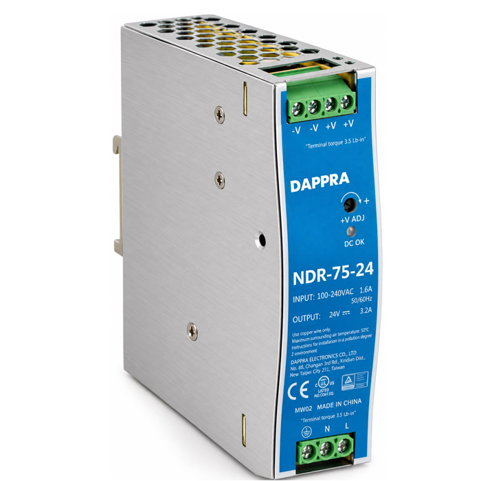
The DAPPRA NDR-75-24 (SKU: OF56) is a 75W single output ultra-slim industrial DIN rail power supply designed for compact industrial control, factory automation and electromechanical applications. It provides a stable 24V DC output at 3.2A rated current from a universal 90–264 VAC input or 127–370 VDC input.
At only 32 mm wide, the NDR-75-24 is the narrowest in the NDR Series, making it ideal for control cabinets where DIN rail space is at a premium. The metal housing enhances power dissipation, and fanless natural convection cooling eliminates dust intake and moving parts. Complete protection functions include short circuit, overload (constant current limiting), over voltage (29–33V) and over temperature protection. Designed for TS35/7.5 or TS35/15 DIN rail mounting and certified to UL508, the NDR-75-24 is an economical 24V power solution for compact industrial loads.
Key Features
NDR-75-24 Key Features
Engineered for economical, ultra-compact 24V industrial power supply applications.
- 76.8W Output · 24V / 3.2ASingle output configuration providing 24V DC nominal output at 3.2A rated current (0~3.2A current range) with 76.8W rated output power.
- Universal AC Input 90–264 VACFull-range single-phase AC input supports global mains voltages. Also supports 127–370 VDC input (DC operation by connecting AC/L(+) and AC/N(−)).
- 24~28V Output AdjustmentFront-panel +V ADJ potentiometer allows the rated output voltage to be adjusted between 24V and 28V to suit the connected load.
- 88% Typical EfficiencyThe NDR-75-24 achieves 88% typical efficiency, reducing energy consumption and heat generation inside the control cabinet.
- Ultra-Slim 32 mm Metal HousingThe 32 × 125.2 × 102 mm metal housing is the narrowest in the NDR Series, saving valuable DIN rail space in compact control cabinets.
- Fanless Natural Convection CoolingNo fan means no dust intake, no acoustic noise and no moving parts — ideal for dusty industrial environments and silent operation.
- Complete Protection FunctionsShort circuit protection, overload protection (105–130% rated output power, constant current limiting, auto-recovery), over voltage protection (29–33V, shut down and re-power) and over temperature protection are built in.
- TS35 DIN Rail MountingDesigned for standard TS35/7.5 or TS35/15 DIN rail mounting inside electrical panels, control cabinets and automation equipment.
- UL508 & Industrial Immunity ApprovedCertified to UL508, TUV BS EN/EN62368-1 and EAC TP TC 004, and complies with BS EN/EN61000-6-2 industrial immunity level.
- 3-Year WarrantyEach NDR-75-24 unit is backed by a 3-year DAPPRA warranty.
Specifications
NDR-75-24 Specifications
Complete technical specifications for the NDR-75-24 industrial DIN rail power supply.
Output
| DC Output Voltage | 24V |
| Rated Current | 3.2A |
| Current Range | 0~3.2A |
| Rated Power | 76.8W |
| Ripple & Noise (max.) | 120mVp-p |
| Voltage Adjustment Range | 24~28V |
| Voltage Tolerance | ±1.0% |
| Line Regulation | ±0.5% |
| Load Regulation | ±1.0% |
| Setup, Rise Time | 1200ms, 60ms/230VAC · 2000ms, 60ms/115VAC at full load |
| Hold Up Time (Typ.) | 60ms/230VAC · 12ms/115VAC at full load |
Input
| Voltage Range | 90~264VAC · 127~370VDC |
| Frequency Range | 47~63Hz |
| Efficiency (Typ.) | 88% |
| AC Current (Typ.) | 1.45A/115VAC · 0.9A/230VAC |
| Inrush Current (Typ.) | 20A/115VAC · 35A/230VAC |
| Leakage Current | <1mA/240VAC |
Protection
| Overload | 105~130% rated output power · Constant current limiting · Auto-recovery |
| Over Voltage | 29~33V · Shut down output, re-power on to recover |
| Over Temperature | Shut down output; re-power on to recover |
| Short Circuit | Protected |
Environment
| Working Temperature | −20 ~ +70°C (Full load up to 50°C, derating above) |
| Working Humidity | 20~95% RH non-condensing |
| Storage Temp., Humidity | −40 ~ +85°C, 10~95% RH |
| Temp. Coefficient | ±0.03%/°C (0~50°C) |
| Vibration | 10~500Hz, 2G 10min./1cycle, 60min. each along X, Y, Z axes |
Safety & EMC
| Safety Standards | UL508, TUV BS EN/EN62368-1, EAC TP TC 004 |
| Withstand Voltage | I/P-O/P: 3KVAC · I/P-FG: 2KVAC · O/P-FG: 0.5KVAC |
| Isolation Resistance | >100M Ohms / 500VDC / 25°C / 70% RH |
| EMC Emission | BS EN/EN55032 (CISPR32) Class A · BS EN/EN61000-3-2,-3 |
| EMC Immunity | BS EN/EN61000-4-2, 3, 4, 5, 6, 8, 11 · BS EN/EN61000-6-2 (BS EN/EN50082-2) heavy industry level |
Reliability & Dimensions
| MTBF | 456.3K hrs min. MIL-HDBK-217F (25°C) |
| Dimensions (W×H×D) | 32 × 125.2 × 102 mm |
| Weight | 0.5 Kg (approx.) |
| Packing | 0.51Kg; 28pcs/15.3Kg/1.22CUFT |
| Warranty | 3 Years |
Front Panel Controls
| +V ADJ | Output voltage adjustment potentiometer (24~28V) |
| DC OK | DC output OK indicator LED |
| Terminal TB1 | Input: FG / AC-N-DC− / AC-L-DC+ |
| Terminal TB2 | Output: −V (pins 1,2) / +V (pins 3,4) |
Notes
1. All parameters not specially mentioned are measured at 230VAC input, rated load and 25°C ambient temperature. 2. Ripple & noise are measured at 20MHz of bandwidth with a 12" twisted pair-wire terminated with a 0.1μF & 47μF parallel capacitor. 3. Tolerance includes set-up tolerance, line regulation and load regulation. 4. The power supply is considered a component to be installed into a final equipment; the final equipment must be re-confirmed to meet EMC directives. 5. Derating may be needed under low input voltage. 6. The NDR-75-24 does not include active PFC; active PFC is available on NDR-240 and NDR-480 models only. 7. Full-load operation is specified up to 50°C ambient; derating is required above 50°C according to the derating curve.
Model Information
NDR-75-24 Model Code
The model number identifies the NDR Series, output wattage and output voltage. DAPPRA SKU for this model: OF56.
Model Code
NDR
-
75
-
24
NDRSeries prefix — DAPPRA NDR Series Slim DIN Rail Power Supply.
75 — Output WattageOutput power rating in Watts. This model provides 76.8W at 24V / 3.2A.
24 — Output VoltageNominal output voltage in VDC. This model provides 24V DC output.
Field
Meaning
Value
NDR
Series prefix
NDR
Output Wattage
Rated output power in Watts
76.8W
Output Voltage
Nominal DC output voltage
24V
Example: NDR-75-24 = NDR Series, 75W class, 24V DC output. Actual rated power: 76.8W (24V × 3.2A). DAPPRA SKU: OF56.
Dimensions
NDR-75-24 Dimensions
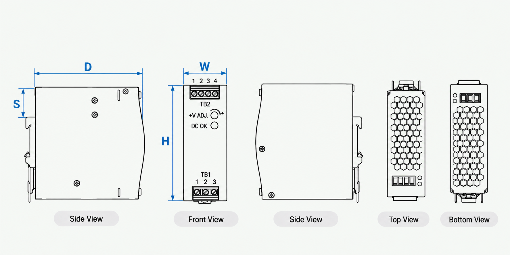
Ultra-slim 32 mm metal housing — the narrowest in the NDR Series — designed for space-constrained control cabinets. All dimensions in mm, tolerance ±1 mm.
Mechanical Dimensions
| Width (W) | 32 mm |
| Height (H) | 125.2 mm |
| Depth (D) | 102 mm |
| DIN Rail Slot to Top (S) | 35 mm |
| Weight | 0.5 Kg (approx.) |
| Front Panel | +V ADJ / DC OK |
Installation Clearances
| Top Clearance | 40 mm |
| Bottom Clearance | 20 mm |
| Left / Right Clearance | 5 mm |
| Adjacent Heat Source | 15 mm recommended |
| DIN Rail | TS35/7.5 or TS35/15 |
| Mounting Orientation | Vertical only (input bottom, output top) |
Installation
NDR-75-24 Installation
The NDR-75-24 supports TS35 DIN rail mounting with specific ventilation clearance and orientation requirements for reliable operation.
01 / 06
Vertical Orientation Only
The appropriate mounting orientation is vertical — input terminals at the bottom and output terminals at the top. Upside-down, horizontal or table-top mounting is not allowed, as sufficient cooling will not be possible.
02 / 06
Ventilation Clearance
Always allow good ventilation clearances around the unit: 5 mm left and right, 40 mm above and 20 mm below, to prevent overheating. When the adjacent device is a heat source, keep 15 mm clearance.
03 / 06
TS35 DIN Rail Mounting
Admissible DIN rail: TS35/7.5 or TS35/15. Tilt the unit slightly rearwards, fit over the top hat rail, slide it downward until it hits the stop, press against the bottom for locking, then shake slightly to check the locking action.
04 / 06
FG Must Be Connected to PE
The FG (Frame Ground) terminal must be connected to PE (Protective Earth) for safety and to ensure proper EMC performance.
05 / 06
Operating Temperature Limits
The NDR-75-24 operates from −20°C to +70°C, with full-load operation specified up to 50°C ambient. Load derating is required above 50°C according to the derating curve.
06 / 06
Pollution Degree 2 Environment
Install the unit only in a pollution degree 2 environment — typically dry, well-ventilated locations such as control cabinets. Do not install in places with high moisture or near water.

Wiring & Terminal
NDR-75-24 Wiring & Terminal
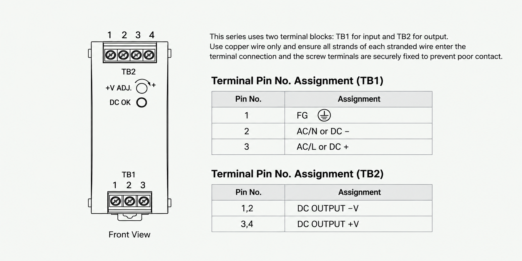
The NDR-75-24 uses two terminal blocks: TB1 for input and TB2 for output. Use copper wire only and ensure all strands of each stranded wire enter the terminal connection and the screw terminals are securely fixed to prevent poor contact.
Terminal Pin Assignment
TB1 — Input Terminal
| Pin No. | Assignment |
|---|---|
| 1 | FG (Frame Ground) |
| 2 | AC/N or DC− |
| 3 | AC/L or DC+ |
TB2 — Output Terminal
| Pin No. | Assignment |
|---|---|
| 1, 2 | DC OUTPUT −V |
| 3, 4 | DC OUTPUT +V |
The FG pin must be connected to PE (Protective Earth). Both −V pins (1, 2) and both +V pins (3, 4) should be connected to their respective output wires to prevent excessive current stress on a single contact. DC input operation is possible by connecting AC/L(+), AC/N(−).
Wiring Specification
Recommended Wire
| AWG | Rated Current | Cross-section |
|---|---|---|
| 18 | 7 A | 0.8 mm² |
| 16 | 10 A | 1.3 mm² |
| 14 | 15 A | 2.1 mm² |
| 12 | 20 A | 3.3 mm² |
Current each wire carries should be de-rated to 80% of the current suggested above when using 5 or more wires connected to the unit. Use wires that can withstand temperatures of at least 80°C, such as UL1007.
Terminal Torque Setting
| Model | I/P | O/P |
|---|---|---|
| NDR-75 | 6.9 kgf-cm (6 Lb-in) | 6.9 kgf-cm (6 Lb-in) |
Recommended wire strapping length: 5 mm (0.197"). Recommended screwdriver: 3 mm, slotted type.
Fuse & Circuit Breaker (230V)
| Model | Fuse | C16 | D16 |
|---|---|---|---|
| NDR-75 | T3.15A/L250V | 6 | 13 |
Maximum number of NDR-75 PSUs that can be connected to a circuit breaker at 230V. For continued protection against risk of fire, replace only with the same type and rating of fuse.
DC Output Voltage Adjustment
The NDR-75-24 includes a front-panel DC output voltage adjustment potentiometer (+V ADJ) and a DC OK indicator LED. The rated output voltage can be adjusted between 24V and 28V via the front-panel adjuster. Output current and output wattage must not exceed the rated value on its specification.
Safety & Compliance
NDR-75-24 Safety & Cautions
Read and follow all safety instructions before installing, wiring, maintaining or modifying the NDR-75-24 power supply.
- Risk of electrical shock and energy hazard. All failure should be examined by a qualified technician. Do not remove the case of the power supply yourself.
- Connecting both the primary and the secondary sides together is not allowed — risk of electric arcs and electric shock (danger to life).
- Risk of burn hazard. Do not touch the unit in operation and shortly after disconnection.
- Risk of fire and short circuit. The openings should be protected from foreign objects or dripping liquids.
- The FG (Frame Ground) must be connected to PE (Protective Earth).
- Output current and output wattage must not exceed the rated value on its specification.
- Before commencing any installation, maintenance or modification work, disconnect the system from supply voltage. Make sure that inadvertent connection in circuit will be impossible.
- For continued protection against risk of fire, replace only with the same type and rating of fuse.
- The power supply is considered a component which will be installed into a final equipment. The final equipment must be re-confirmed that it still meets EMC directives.
Note: Pollution Degree 2 applies where there is only non-conductive pollution that might temporarily become conductive due to occasional condensation. Generally refers to dry, well-ventilated locations, such as control cabinets.
Applications
NDR-75-24 Industrial Applications
The NDR-75-24 is suitable for compact industrial control systems, factory automation equipment, electromechanical apparatus, electrical panels and sensor power circuits.
Industrial Control Systems
Factory Automation
Electromechanical Apparatus
Electrical Panels
Semiconductor Equipment
Machine Control
Process Control
Test & Measurement
Building Automation
PLC & Sensor Power
Industrial LED Lighting
Security & Access Control
Next Step
Need the NDR-75-24 for Your Application?
Contact DAPPRA Automation for product specifications, installation support, technical documentation and purchasing assistance — or explore the full NDR Series and industrial power supply range.
Support
NDR-75-24 FAQ
What is the DAPPRA NDR-75-24?
The DAPPRA NDR-75-24 (SKU: OF56) is a 75W industrial DIN rail power supply designed to provide 24V DC at 3.2A for compatible industrial control equipment. Its 32mm-wide housing helps save space inside electrical control cabinets.
What are the rated output voltage and current of the NDR-75-24?
The NDR-75-24 provides a nominal output of 24V DC at a rated current of 3.2A, with a rated output power of 76.8W. Select the connected load so that its current and power requirements remain within these rated limits.
Is the NDR-75-24 suitable for a 24V PLC control circuit?
It can be used for a compatible 24V DC PLC control circuit if the PLC's input voltage requirements and total current consumption are within the power supply's ratings. Check the PLC and accessory specifications before installation.
Can the NDR-75-24 supply several 24V sensors and relays at the same time?
Yes, provided that the combined load remains within the rated output capacity of 3.2A / 76.8W. Calculate the total steady-state current and consider startup demand before connecting multiple sensors, relays, or other devices.
Can the output voltage of the NDR-75-24 be adjusted?
Yes. The front-panel +V ADJ potentiometer allows the output voltage to be adjusted from 24V to 28V DC. Check the voltage limits of every connected device before changing the setting.
What input voltage does the NDR-75-24 support?
The NDR-75-24 supports a single-phase AC input range of 90–264VAC at 47–63Hz and a DC input range of 127–370VDC. DC input operation is possible by connecting AC/L(+) and AC/N(−).
What is the typical efficiency of the NDR-75-24?
The NDR-75-24 has a typical efficiency of 88%. Actual efficiency can vary with input voltage and load conditions.
Does the NDR-75-24 have active PFC?
No. The NDR-75-24 does not include built-in active power factor correction (PFC). It conforms to BS EN/EN61000-3-2 harmonic current requirements. Within the NDR Series, active PFC is available only on the NDR-240 and NDR-480 models.
What happens if the connected load draws too much current on the NDR-75-24?
The NDR-75-24 includes overload protection rated at 105–130% of rated output power, using constant-current limiting with automatic recovery after the fault condition is removed.
Does the NDR-75-24 provide short-circuit and overvoltage protection?
Yes. The NDR-75-24 includes short-circuit protection and overvoltage protection set at 29–33V. When overvoltage is triggered, the output shuts down and re-powering is required to recover.
Does the NDR-75-24 require a cooling fan?
No. The NDR Series uses fanless natural-convection cooling. Maintain adequate ventilation around the unit and follow the specified installation clearances to help prevent excessive heat buildup.
How much DIN rail space does the NDR-75-24 occupy?
The NDR-75-24 has a slim 32mm-wide housing and measures 32 × 125.2 × 102 mm (W × H × D). Allow sufficient clearance for wiring and heat dissipation.
Which DIN rail types are compatible with the NDR-75-24?
The NDR-75-24 is designed for TS35/7.5 and TS35/15 DIN rail mounting. Confirm the rail profile and mounting arrangement in your control cabinet before installation.
Can the NDR-75-24 replace an existing 24V power supply?
It may be suitable if the replacement has compatible input requirements, a 24V DC output, sufficient current capacity, suitable mounting dimensions, and compatible terminal wiring. Check the existing load and wiring diagram before replacing the unit.
How can I confirm whether the NDR-75-24 suits my application?
Provide your equipment model, required 24V load current, input power source, and installation requirements to DAPPRA. This information helps verify compatibility before ordering.
Mungkin Anda suka
-

-

-

-
DRM-0840-R Relay Safety Light Curtain Industrial Area Sensor
Rp2,300,000.00 -
DRM-1020-R Relay Safety Light Curtain Industrial Area Sensor
Rp1,520,000.00 -
DRM-0620-R Relay Safety Light Curtain Industrial Area Sensor
Rp1,300,000.00


Overview
NDR-75-24 Overview
The DAPPRA NDR-75-24 (SKU: OF56) is a 75W single output ultra-slim industrial DIN rail power supply designed for compact industrial control, factory automation and electromechanical applications. It provides a stable 24V DC output at 3.2A rated current from a universal 90–264 VAC input or 127–370 VDC input.
At only 32 mm wide, the NDR-75-24 is the narrowest in the NDR Series, making it ideal for control cabinets where DIN rail space is at a premium. The metal housing enhances power dissipation, and fanless natural convection cooling eliminates dust intake and moving parts. Complete protection functions include short circuit, overload (constant current limiting), over voltage (29–33V) and over temperature protection. Designed for TS35/7.5 or TS35/15 DIN rail mounting and certified to UL508, the NDR-75-24 is an economical 24V power solution for compact industrial loads.
Key Features
NDR-75-24 Key Features
Engineered for economical, ultra-compact 24V industrial power supply applications.
- 76.8W Output · 24V / 3.2ASingle output configuration providing 24V DC nominal output at 3.2A rated current (0~3.2A current range) with 76.8W rated output power.
- Universal AC Input 90–264 VACFull-range single-phase AC input supports global mains voltages. Also supports 127–370 VDC input (DC operation by connecting AC/L(+) and AC/N(−)).
- 24~28V Output AdjustmentFront-panel +V ADJ potentiometer allows the rated output voltage to be adjusted between 24V and 28V to suit the connected load.
- 88% Typical EfficiencyThe NDR-75-24 achieves 88% typical efficiency, reducing energy consumption and heat generation inside the control cabinet.
- Ultra-Slim 32 mm Metal HousingThe 32 × 125.2 × 102 mm metal housing is the narrowest in the NDR Series, saving valuable DIN rail space in compact control cabinets.
- Fanless Natural Convection CoolingNo fan means no dust intake, no acoustic noise and no moving parts — ideal for dusty industrial environments and silent operation.
- Complete Protection FunctionsShort circuit protection, overload protection (105–130% rated output power, constant current limiting, auto-recovery), over voltage protection (29–33V, shut down and re-power) and over temperature protection are built in.
- TS35 DIN Rail MountingDesigned for standard TS35/7.5 or TS35/15 DIN rail mounting inside electrical panels, control cabinets and automation equipment.
- UL508 & Industrial Immunity ApprovedCertified to UL508, TUV BS EN/EN62368-1 and EAC TP TC 004, and complies with BS EN/EN61000-6-2 industrial immunity level.
- 3-Year WarrantyEach NDR-75-24 unit is backed by a 3-year DAPPRA warranty.
Specifications
NDR-75-24 Specifications
Complete technical specifications for the NDR-75-24 industrial DIN rail power supply.
Output
| DC Output Voltage | 24V |
| Rated Current | 3.2A |
| Current Range | 0~3.2A |
| Rated Power | 76.8W |
| Ripple & Noise (max.) | 120mVp-p |
| Voltage Adjustment Range | 24~28V |
| Voltage Tolerance | ±1.0% |
| Line Regulation | ±0.5% |
| Load Regulation | ±1.0% |
| Setup, Rise Time | 1200ms, 60ms/230VAC · 2000ms, 60ms/115VAC at full load |
| Hold Up Time (Typ.) | 60ms/230VAC · 12ms/115VAC at full load |
Input
| Voltage Range | 90~264VAC · 127~370VDC |
| Frequency Range | 47~63Hz |
| Efficiency (Typ.) | 88% |
| AC Current (Typ.) | 1.45A/115VAC · 0.9A/230VAC |
| Inrush Current (Typ.) | 20A/115VAC · 35A/230VAC |
| Leakage Current | <1mA/240VAC |
Protection
| Overload | 105~130% rated output power · Constant current limiting · Auto-recovery |
| Over Voltage | 29~33V · Shut down output, re-power on to recover |
| Over Temperature | Shut down output; re-power on to recover |
| Short Circuit | Protected |
Environment
| Working Temperature | −20 ~ +70°C (Full load up to 50°C, derating above) |
| Working Humidity | 20~95% RH non-condensing |
| Storage Temp., Humidity | −40 ~ +85°C, 10~95% RH |
| Temp. Coefficient | ±0.03%/°C (0~50°C) |
| Vibration | 10~500Hz, 2G 10min./1cycle, 60min. each along X, Y, Z axes |
Safety & EMC
| Safety Standards | UL508, TUV BS EN/EN62368-1, EAC TP TC 004 |
| Withstand Voltage | I/P-O/P: 3KVAC · I/P-FG: 2KVAC · O/P-FG: 0.5KVAC |
| Isolation Resistance | >100M Ohms / 500VDC / 25°C / 70% RH |
| EMC Emission | BS EN/EN55032 (CISPR32) Class A · BS EN/EN61000-3-2,-3 |
| EMC Immunity | BS EN/EN61000-4-2, 3, 4, 5, 6, 8, 11 · BS EN/EN61000-6-2 (BS EN/EN50082-2) heavy industry level |
Reliability & Dimensions
| MTBF | 456.3K hrs min. MIL-HDBK-217F (25°C) |
| Dimensions (W×H×D) | 32 × 125.2 × 102 mm |
| Weight | 0.5 Kg (approx.) |
| Packing | 0.51Kg; 28pcs/15.3Kg/1.22CUFT |
| Warranty | 3 Years |
Front Panel Controls
| +V ADJ | Output voltage adjustment potentiometer (24~28V) |
| DC OK | DC output OK indicator LED |
| Terminal TB1 | Input: FG / AC-N-DC− / AC-L-DC+ |
| Terminal TB2 | Output: −V (pins 1,2) / +V (pins 3,4) |
Notes
1. All parameters not specially mentioned are measured at 230VAC input, rated load and 25°C ambient temperature. 2. Ripple & noise are measured at 20MHz of bandwidth with a 12" twisted pair-wire terminated with a 0.1μF & 47μF parallel capacitor. 3. Tolerance includes set-up tolerance, line regulation and load regulation. 4. The power supply is considered a component to be installed into a final equipment; the final equipment must be re-confirmed to meet EMC directives. 5. Derating may be needed under low input voltage. 6. The NDR-75-24 does not include active PFC; active PFC is available on NDR-240 and NDR-480 models only. 7. Full-load operation is specified up to 50°C ambient; derating is required above 50°C according to the derating curve.
Model Information
NDR-75-24 Model Code
The model number identifies the NDR Series, output wattage and output voltage. DAPPRA SKU for this model: OF56.
Model Code
NDR
-
75
-
24
NDRSeries prefix — DAPPRA NDR Series Slim DIN Rail Power Supply.
75 — Output WattageOutput power rating in Watts. This model provides 76.8W at 24V / 3.2A.
24 — Output VoltageNominal output voltage in VDC. This model provides 24V DC output.
Field
Meaning
Value
NDR
Series prefix
NDR
Output Wattage
Rated output power in Watts
76.8W
Output Voltage
Nominal DC output voltage
24V
Example: NDR-75-24 = NDR Series, 75W class, 24V DC output. Actual rated power: 76.8W (24V × 3.2A). DAPPRA SKU: OF56.
Dimensions
NDR-75-24 Dimensions
Ultra-slim 32 mm metal housing — the narrowest in the NDR Series — designed for space-constrained control cabinets. All dimensions in mm, tolerance ±1 mm.
Mechanical Dimensions
| Width (W) | 32 mm |
| Height (H) | 125.2 mm |
| Depth (D) | 102 mm |
| DIN Rail Slot to Top (S) | 35 mm |
| Weight | 0.5 Kg (approx.) |
| Front Panel | +V ADJ / DC OK |
Installation Clearances
| Top Clearance | 40 mm |
| Bottom Clearance | 20 mm |
| Left / Right Clearance | 5 mm |
| Adjacent Heat Source | 15 mm recommended |
| DIN Rail | TS35/7.5 or TS35/15 |
| Mounting Orientation | Vertical only (input bottom, output top) |
Installation
NDR-75-24 Installation
The NDR-75-24 supports TS35 DIN rail mounting with specific ventilation clearance and orientation requirements for reliable operation.
01 / 06
Vertical Orientation Only
The appropriate mounting orientation is vertical — input terminals at the bottom and output terminals at the top. Upside-down, horizontal or table-top mounting is not allowed, as sufficient cooling will not be possible.
02 / 06
Ventilation Clearance
Always allow good ventilation clearances around the unit: 5 mm left and right, 40 mm above and 20 mm below, to prevent overheating. When the adjacent device is a heat source, keep 15 mm clearance.
03 / 06
TS35 DIN Rail Mounting
Admissible DIN rail: TS35/7.5 or TS35/15. Tilt the unit slightly rearwards, fit over the top hat rail, slide it downward until it hits the stop, press against the bottom for locking, then shake slightly to check the locking action.
04 / 06
FG Must Be Connected to PE
The FG (Frame Ground) terminal must be connected to PE (Protective Earth) for safety and to ensure proper EMC performance.
05 / 06
Operating Temperature Limits
The NDR-75-24 operates from −20°C to +70°C, with full-load operation specified up to 50°C ambient. Load derating is required above 50°C according to the derating curve.
06 / 06
Pollution Degree 2 Environment
Install the unit only in a pollution degree 2 environment — typically dry, well-ventilated locations such as control cabinets. Do not install in places with high moisture or near water.
Wiring & Terminal
NDR-75-24 Wiring & Terminal
The NDR-75-24 uses two terminal blocks: TB1 for input and TB2 for output. Use copper wire only and ensure all strands of each stranded wire enter the terminal connection and the screw terminals are securely fixed to prevent poor contact.
Terminal Pin Assignment
TB1 — Input Terminal
| Pin No. | Assignment |
|---|---|
| 1 | FG (Frame Ground) |
| 2 | AC/N or DC− |
| 3 | AC/L or DC+ |
TB2 — Output Terminal
| Pin No. | Assignment |
|---|---|
| 1, 2 | DC OUTPUT −V |
| 3, 4 | DC OUTPUT +V |
The FG pin must be connected to PE (Protective Earth). Both −V pins (1, 2) and both +V pins (3, 4) should be connected to their respective output wires to prevent excessive current stress on a single contact. DC input operation is possible by connecting AC/L(+), AC/N(−).
Wiring Specification
Recommended Wire
| AWG | Rated Current | Cross-section |
|---|---|---|
| 18 | 7 A | 0.8 mm² |
| 16 | 10 A | 1.3 mm² |
| 14 | 15 A | 2.1 mm² |
| 12 | 20 A | 3.3 mm² |
Current each wire carries should be de-rated to 80% of the current suggested above when using 5 or more wires connected to the unit. Use wires that can withstand temperatures of at least 80°C, such as UL1007.
Terminal Torque Setting
| Model | I/P | O/P |
|---|---|---|
| NDR-75 | 6.9 kgf-cm (6 Lb-in) | 6.9 kgf-cm (6 Lb-in) |
Recommended wire strapping length: 5 mm (0.197"). Recommended screwdriver: 3 mm, slotted type.
Fuse & Circuit Breaker (230V)
| Model | Fuse | C16 | D16 |
|---|---|---|---|
| NDR-75 | T3.15A/L250V | 6 | 13 |
Maximum number of NDR-75 PSUs that can be connected to a circuit breaker at 230V. For continued protection against risk of fire, replace only with the same type and rating of fuse.
DC Output Voltage Adjustment
The NDR-75-24 includes a front-panel DC output voltage adjustment potentiometer (+V ADJ) and a DC OK indicator LED. The rated output voltage can be adjusted between 24V and 28V via the front-panel adjuster. Output current and output wattage must not exceed the rated value on its specification.
Safety & Compliance
NDR-75-24 Safety & Cautions
Read and follow all safety instructions before installing, wiring, maintaining or modifying the NDR-75-24 power supply.
- Risk of electrical shock and energy hazard. All failure should be examined by a qualified technician. Do not remove the case of the power supply yourself.
- Connecting both the primary and the secondary sides together is not allowed — risk of electric arcs and electric shock (danger to life).
- Risk of burn hazard. Do not touch the unit in operation and shortly after disconnection.
- Risk of fire and short circuit. The openings should be protected from foreign objects or dripping liquids.
- The FG (Frame Ground) must be connected to PE (Protective Earth).
- Output current and output wattage must not exceed the rated value on its specification.
- Before commencing any installation, maintenance or modification work, disconnect the system from supply voltage. Make sure that inadvertent connection in circuit will be impossible.
- For continued protection against risk of fire, replace only with the same type and rating of fuse.
- The power supply is considered a component which will be installed into a final equipment. The final equipment must be re-confirmed that it still meets EMC directives.
Note: Pollution Degree 2 applies where there is only non-conductive pollution that might temporarily become conductive due to occasional condensation. Generally refers to dry, well-ventilated locations, such as control cabinets.
Applications
NDR-75-24 Industrial Applications
The NDR-75-24 is suitable for compact industrial control systems, factory automation equipment, electromechanical apparatus, electrical panels and sensor power circuits.
Industrial Control Systems
Factory Automation
Electromechanical Apparatus
Electrical Panels
Semiconductor Equipment
Machine Control
Process Control
Test & Measurement
Building Automation
PLC & Sensor Power
Industrial LED Lighting
Security & Access Control
Next Step
Need the NDR-75-24 for Your Application?
Contact DAPPRA Automation for product specifications, installation support, technical documentation and purchasing assistance — or explore the full NDR Series and industrial power supply range.
Support
NDR-75-24 FAQ
What is the DAPPRA NDR-75-24?
The DAPPRA NDR-75-24 (SKU: OF56) is a 75W industrial DIN rail power supply designed to provide 24V DC at 3.2A for compatible industrial control equipment. Its 32mm-wide housing helps save space inside electrical control cabinets.
What are the rated output voltage and current of the NDR-75-24?
The NDR-75-24 provides a nominal output of 24V DC at a rated current of 3.2A, with a rated output power of 76.8W. Select the connected load so that its current and power requirements remain within these rated limits.
Is the NDR-75-24 suitable for a 24V PLC control circuit?
It can be used for a compatible 24V DC PLC control circuit if the PLC's input voltage requirements and total current consumption are within the power supply's ratings. Check the PLC and accessory specifications before installation.
Can the NDR-75-24 supply several 24V sensors and relays at the same time?
Yes, provided that the combined load remains within the rated output capacity of 3.2A / 76.8W. Calculate the total steady-state current and consider startup demand before connecting multiple sensors, relays, or other devices.
Can the output voltage of the NDR-75-24 be adjusted?
Yes. The front-panel +V ADJ potentiometer allows the output voltage to be adjusted from 24V to 28V DC. Check the voltage limits of every connected device before changing the setting.
What input voltage does the NDR-75-24 support?
The NDR-75-24 supports a single-phase AC input range of 90–264VAC at 47–63Hz and a DC input range of 127–370VDC. DC input operation is possible by connecting AC/L(+) and AC/N(−).
What is the typical efficiency of the NDR-75-24?
The NDR-75-24 has a typical efficiency of 88%. Actual efficiency can vary with input voltage and load conditions.
Does the NDR-75-24 have active PFC?
No. The NDR-75-24 does not include built-in active power factor correction (PFC). It conforms to BS EN/EN61000-3-2 harmonic current requirements. Within the NDR Series, active PFC is available only on the NDR-240 and NDR-480 models.
What happens if the connected load draws too much current on the NDR-75-24?
The NDR-75-24 includes overload protection rated at 105–130% of rated output power, using constant-current limiting with automatic recovery after the fault condition is removed.
Does the NDR-75-24 provide short-circuit and overvoltage protection?
Yes. The NDR-75-24 includes short-circuit protection and overvoltage protection set at 29–33V. When overvoltage is triggered, the output shuts down and re-powering is required to recover.
Does the NDR-75-24 require a cooling fan?
No. The NDR Series uses fanless natural-convection cooling. Maintain adequate ventilation around the unit and follow the specified installation clearances to help prevent excessive heat buildup.
How much DIN rail space does the NDR-75-24 occupy?
The NDR-75-24 has a slim 32mm-wide housing and measures 32 × 125.2 × 102 mm (W × H × D). Allow sufficient clearance for wiring and heat dissipation.
Which DIN rail types are compatible with the NDR-75-24?
The NDR-75-24 is designed for TS35/7.5 and TS35/15 DIN rail mounting. Confirm the rail profile and mounting arrangement in your control cabinet before installation.
Can the NDR-75-24 replace an existing 24V power supply?
It may be suitable if the replacement has compatible input requirements, a 24V DC output, sufficient current capacity, suitable mounting dimensions, and compatible terminal wiring. Check the existing load and wiring diagram before replacing the unit.
How can I confirm whether the NDR-75-24 suits my application?
Provide your equipment model, required 24V load current, input power source, and installation requirements to DAPPRA. This information helps verify compatibility before ordering.
4 ulasan untuk NDR-75-24 75W 24V 3.2A Industrial DIN Rail Power Supply
-
barang sesuai gambar, pengiran cepat, kurir ramah, Terima kasih sukses selalu buat penjual nya.
-
ok
-
pengiriman cepat rapi…
-

Hanya pelanggan yang telah membeli produk ini dapat memberikan ulasan.


Eko ****** (pemilik terverifikasi) –
barang sesuai gambar, pengiran cepat, kurir ramah, Terima kasih sukses selalu buat penjual nya.
R**** (pemilik terverifikasi) –
ok
sugi**** (pemilik terverifikasi) –
pengiriman cepat rapi…
slam** (pemilik terverifikasi) –