Tidak ada produk di keranjang.

Ultrasonic Level Sensor Waterproof Distance Measuring Controller SR94 User Manual
Product Overview
The SR94 waterproof ultrasonic long-range sensing module is designed for distance and level measurement using ultrasonic time-of-flight technology. The module integrates a high-performance processor and high-quality components to ensure stable operation and long service life.
It adopts a fully sealed waterproof ultrasonic transducer, providing strong environmental adaptability. When used with the dedicated horn structure, the sensor supports longer measurement ranges.
The SR94 series offers multiple output modes and is a high-performance, highly reliable commercial-grade sensing module that is easy to operate and integrate.
Product Features
- Operating voltage options: 3.3V–5V; RS485 version supports 5V–12V
- Output modes:
- UART automatic output
- UART triggered output
- PWM automatic output
- PWM triggered output
- Switch output
- RS485 output
- Standby current can be lower than 10µA
- Fully sealed waterproof sensor head
- Built-in temperature compensation
- Operating temperature: –15°C to +60°C
- Storage temperature: –25°C to +80°C
- Measurement accuracy: ±(1cm + S × 0.3%), where S is the measured distance
- Built-in ESD protection on sensor housing and I/O pins, meeting IEC61000-4-2 requirements
Product Advantages
- High protection level
- Strong anti-interference capability
- Stable and reliable output data
- Low power consumption
- High ESD resistance
- High measurement accuracy
- Compact size and easy installation
- Automatic output mode reduces workload on the host processor
- Trigger-controlled mode enables optimized low-power operation
Application Fields
- Horizontal distance measurement
- Water level and liquid level monitoring
- Parking systems
- Object detection and presence sensing
- Smart waste bin level monitoring
- Robotics obstacle avoidance and automation control
- Sewer and well water-level monitoring
Basic Specifications
(SR94 values derived from the original flat-surface measurement model)
| Parameter | Value | Unit | Notes |
|---|---|---|---|
| Operating Voltage | 3.3–5V (RS485: 5–12V) | V | — |
| Average Current | <10 | mA | Typical at 5V, 100ms cycle |
| Blind Zone | ≤28 | cm | — |
| Range (without horn) | 28–450 | cm | Flat surface measurement |
| Range (with horn) | 28–750 | cm | Extended range |
| Beam Angle (without horn) | ≈75° | — | Reference value |
| Beam Angle (with horn) | ≈40° | — | Reference value |
| Output Methods | UART Auto / UART Triggered / PWM Auto / PWM Triggered / Switch Output / RS485 | — | — |
Wiring Definition
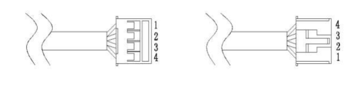
| Pin | Name | Description |
|---|---|---|
| 1 | VCC | Power input |
| 2 | GND | Ground |
| 3 | RX | Function pin (depends on output mode) |
| 4 | TX | Function pin (depends on output mode) |
The functionality of RX and TX depends strictly on the selected output mode and cannot be mixed.
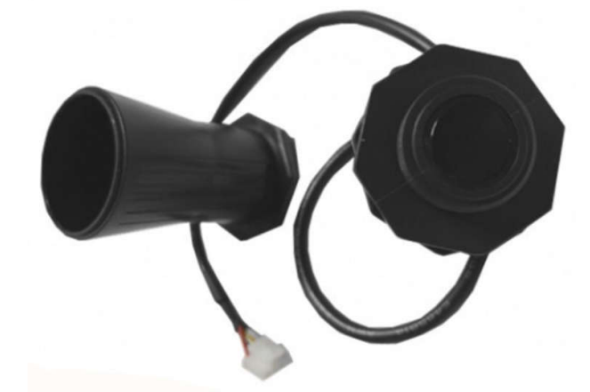
Mechanical Characteristics
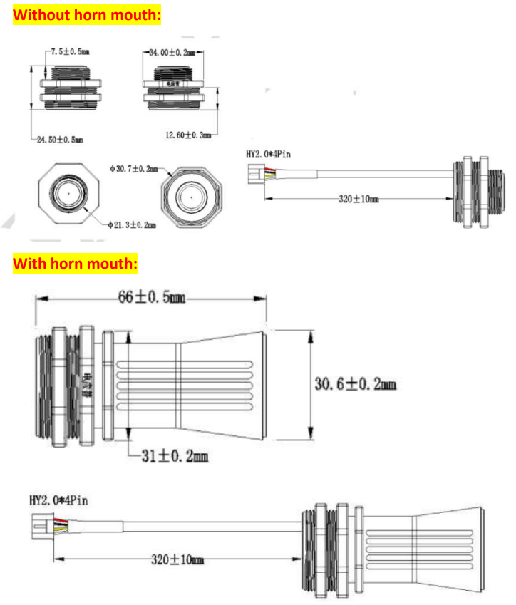
The SR94 module is available in two physical configurations:
1. Without Horn (Standard Version)
- Compact and fully sealed ultrasonic transducer
- Suitable for medium-range measurement applications
2. With Horn (Long-Range Version)
- Extended acoustic structure improves sensitivity and increases maximum range
- Optimized for long-distance flat-surface and liquid-level measurement
Output Methods
The SR94 supports multiple output modes. Each output mode has specific electrical behavior, timing characteristics, and communication formats. The following sections describe each mode in detail.
1. UART Automatic Output Mode
1.1 Wiring Definition
| Pin | Name | Description |
|---|---|---|
| 1 | VCC | Power input |
| 2 | GND | Ground |
| 3 | RX | Selection pin for processed or real-time values |
| 4 | TX | UART output pin |
- RX pin determines the output data type at power-up.
- Pin functions cannot be mixed with other output modes.
1.2 UART Automatic Output Behavior
- When RX is floating or at high level → the module outputs processed values, which are more stable (response time: 300–500 ms).
- When RX is low level at power-up → the module outputs real-time values (response time: 100 ms).
Note: The RX pin is checked only at power-up when selecting between processed and real-time values.
1.3 UART Communication Parameters
- Logic level: TTL
- Data bits: 8
- Stop bit: 1
- Parity: None
- Baud rate: 9600 bps
1.4 UART Data Frame Format
| Byte | Description |
|---|---|
| 0 | Frame Header (0xFF) |
| 1 | Data_H (distance high byte) |
| 2 | Data_L (distance low byte) |
| 3 | Checksum (SUM) |
Checksum:
SUM = (FrameHeader + Data_H + Data_L) & 0x00FF
Distance Calculation:
Distance = Data_H × 256 + Data_L (unit: mm)
1.5 UART Output Example
| Frame Header | Data_H | Data_L | SUM |
|---|---|---|---|
| 0xFF | 0x07 | 0xA1 | 0xA7 |
Checksum example:
SUM = (0xFF + 0x07 + 0xA1) & 0xFF = 0xA7
Distance = 0x07A1 = 1953 mm.
2. UART Triggered Output Mode
2.1 Wiring Definition
| Pin | Name | Description |
|---|---|---|
| 1 | VCC | Power input |
| 2 | GND | Ground |
| 3 | RX | Trigger input pin |
| 4 | TX | UART output pin |
2.2 UART Triggered Measurement Behavior
- A falling-edge pulse on RX or any received UART data triggers a measurement.
- After measurement, distance data is sent through TX.
- Trigger cycle must be ≥ 70 ms for standard measurement.
- Response time for SR94 (liquid-level version):
- Processed value: ~500 ms
- Real-time value: ~100 ms
2.3 UART Communication Parameters
Same as UART Auto Mode.
2.4 Data Frame Format
Identical to UART Automatic Output Mode.
2.5 Output Example
Same numerical example as automatic mode.
3. PWM Automatic Output Mode
3.1 Wiring Definition
| Pin | Name | Description |
|---|---|---|
| 1 | VCC | Power input |
| 2 | GND | Ground |
| 3 | RX | Not used |
| 4 | TX | PWM output |
3.2 PWM Automatic Behavior
- Measurement cycle: 250 ms
- Output pulse width represents measured distance.
- If no target is detected → output is a fixed pulse width of approximately 45 ms.
- Temperature compensation is applied to ensure accuracy in varying environments.
3.3 Distance Calculation
Formula:
S = T × V / 2
Where:
- S = distance (cm)
- T = PWM high-level pulse width (µs)
- V = speed of sound (348 m/s at room temperature)
Simplified formula at room temperature:
S = T / 57.5
Example:
If pulse width T = 10,000 µs →
S = 10000 / 57.5 ≈ 173.9 cm
4. PWM Triggered Output Mode
4.1 Wiring Definition
| Pin | Name | Description |
|---|---|---|
| 1 | VCC | Power input |
| 2 | GND | Ground |
| 3 | RX | Trigger input |
| 4 | TX | PWM output |
4.2 PWM Triggered Behavior
- A falling-edge trigger pulse or UART data initiates a measurement.
- TX outputs one PWM high-level pulse representing the measured distance.
- Trigger period must be ≥ 70 ms.
- If no target is detected → output pulse width ≈ 45 ms.
4.3 Distance Calculation
Same as PWM Automatic Output Mode.
5. Switch Output Mode
5.1 Wiring Definition
| Pin | Name | Description |
|---|---|---|
| 1 | VCC | Power input (3.3–5V) |
| 2 | GND | Ground |
| 3 | RX | Real-time / processed value selection |
| 4 | TX | Switch output pin |
5.2 Switch Output Behavior
- A default threshold distance of 1.5 m is preset at the factory.
- SR94 performs a measurement every 100 ms.
- If measured distance < threshold → TX outputs high level.
- If measured distance ≥ threshold → TX outputs low level.
Response Characteristics:
- RX floating or high → processed values, slower but more stable
- Response: ~1.5 s
- Delay: ~2.5 s
- RX low → real-time values, faster response
- Response: ~0.3 s
- Delay: ~0.5 s
Important:
The module checks RX level only at power-up. Changing mode requires power cycling.
5.3 Threshold Adjustment via UART Command
Data Format:
| Byte | Description |
|---|---|
| 0 | Frame Header (0xFB) |
| 1 | Command (0x05) |
| 2 | Data_H |
| 3 | Data_L |
| 4 | Checksum |
Threshold range: 28–750 cm
6. RS485 Output Mode
6.1 Wiring Definition
| Pin | Name | Description |
|---|---|---|
| 1 | VCC | Power input |
| 2 | GND | Ground |
| 3 | B | RS485 differential negative |
| 4 | A | RS485 differential positive |
Pin functions are fixed and correspond only to the RS485 output version.
6.2 RS485 Interface Parameters
- Electrical level: RS485 differential
- Data bits: 8
- Stop bit: 1
- Parity: None
- Default baud rate: 9600 bps
6.3 Modbus-RTU Protocol Parameters
| Item | Value |
|---|---|
| Mode | Modbus-RTU |
| Error Check | CRC-16/MODBUS |
| Slave Address | Adjustable, default 0x01 |
| Read Function Code | 0x03 |
| Write Function Code | 0x06 |
6.4 Modbus Frame Format
Master → Sensor (Read)
| Field | Device Addr | Func Code (0x03) | Register Addr | Register Count | CRC16 |
|---|
Sensor → Master (Read Response)
| Field | Device Addr | Func Code | Byte Count | Data | CRC16 |
|---|
Master → Sensor (Write)
| Field | Device Addr | Func Code (0x06) | Register Addr | Data | CRC16 |
Sensor → Master (Write Response)
Same format as master write.
6.5 Modbus Register Table
Measurement & Status Registers
| Address | Type | Description | Data Type | Notes |
|---|---|---|---|---|
| 0x0100 | Read-only | Processed distance value | Unsigned 16-bit | Output after algorithm processing; unit: mm; response: 500 ms |
| 0x0101 | Read-only | Real-time distance value | Unsigned 16-bit | Unit: mm; response ~100 ms |
| 0x0102 | Read-only | Temperature | Signed 16-bit | Unit: 0.1°C; resolution 0.5°C |
Configuration Registers
| Address | Type | Description | Data Type | Notes |
|---|---|---|---|---|
| 0x0200 | Read/Write | Slave Address | U16 | Range: 0x01–0xFE (0xFF = broadcast) |
| 0x0201 | Read/Write | Baud Rate | U16 | 0x03=9600 (default); other standard rates supported |
Registers use high-byte–first order.
6.6 RS485 Communication Examples
Example 1: Read processed distance value
Master:01 03 01 00 00 01 85 F6
Response:01 03 02 02 F2 38 A1
Distance: 0x02F2 = 754 mm
Example 2: Read real-time distance
Master:01 03 01 01 00 01 D4 36
Response:01 03 02 02 EF F8 A8
Distance: 0x02EF = 751 mm
Example 3: Read temperature
Master:01 03 01 02 00 01 24 36
Response:01 03 02 01 2C B8 09
Temperature: 0x012C = 30.0°C
Example 4: Change slave address
Master & Sensor Response:01 06 02 00 00 05 48 71
Example 5: Change baud rate
Master & Sensor Response:05 06 02 01 00 01 19 F6
Baud rate set to 2400 bps.
7. Environmental Ratings
7.1 Environmental Limits
| Item | Min | Typical | Max | Unit |
|---|---|---|---|---|
| Storage Temperature | –25 | 25 | 80 | °C |
| Storage Humidity | — | 65% | 90% | RH |
| Operating Temperature | –15 | 25 | 60 | °C |
| Operating Humidity | — | 65% | 80% | RH |
Humidity values specified without condensation.
8. Electrical Ratings
| Parameter | Min | Typical | Max | Unit | Notes |
|---|---|---|---|---|---|
| Operating Voltage | 3.1 | 5.0 | 5.25 | V | (SR94 RS485: 5–12V) |
| Peak Current | — | 50 | 75 | mA | — |
| Input Ripple | — | — | 50 | mV | — |
| Input Noise | — | — | 100 | mV | — |
| ESD Protection | ±200 / ±2k | — | — | V | Contact / Air |
| IEC61000-4-2 ESD | ±4k / ±8k | — | — | V | Sensor housing & I/O |
9. Beam Pattern Reference
9.1 Without Horn
- Wider beam angle
- Suitable for shorter-range detection
- Measurement data based on PVC cylindrical target (7.5cm diameter, 100cm height)
9.2 With Horn
- Narrower beam angle
- Suitable for long-range liquid-level measurement
- Measurement data validated using cardboard box target (60×50 cm)
(Images omitted but content faithfully preserved.)
10. Model Selection Guide (Mapped to SR94 Variants)
The SR94 series includes multiple versions depending on output mode and acoustic structure.
| Application | Features | Output Modes | SR94 Variant |
|---|---|---|---|
| Liquid-Level & Flat-Surface Measurement | Waterproof housing + optional horn; range 28–750 cm; narrow beam | UART Auto / UART Triggered / PWM Auto / PWM Triggered / Switch Output / RS485 | SR94-XXXX (customizable) |
11. Reliability Test Conditions
| Test Item | Conditions | Qty |
|---|---|---|
| High Temp & Humidity Operating | 65°C, 85% RH, power ON for 72h | 3 |
| Low Temp Operating | –20°C, power ON for 72h | 3 |
| High Temp & Humidity Storage | 80°C, 80% RH, 72h | 3 |
| Low Temp Storage | –30°C, 72h | 3 |
| Vibration | 10–200 Hz, 2.0G, XYZ axes | 3 |
| Drop Test | 1.2m free fall, 5 times | 3 |
Pass Criteria: Function normal, performance degradation ≤10%.
12. Notes
- Mechanical tolerance issues may cause temporary functional abnormalities.
- Avoid electromagnetic interference risks; improper system design may affect performance.
- For edge-case or extreme condition applications, technical consultation is recommended.
- Specifications may change without prior notice.
13. Packaging Specifications
- Default packaging is standard industrial packing.
- Custom packaging available upon request.
- For container shipment, staggered stacking and reinforced corner protection are required.
Download Technical Manual
You can download the full technical manual for the SR94 ultrasonic long-range level sensor using the link below:
Download SR94 Manual (PDF)Related Articles
- Industrial Communication Protocols Explained: Modbus, EtherCAT, and Profinet
- MQTT vs Modbus: A Practical Industrial Protocol Selection Guide
- Building an Intelligent Production Line with PLC + HMI + Sensors
- Control Panel Wiring Standards: How to Build a Professional and Clean Control Cabinet
- Control Circuit Troubleshooting: What to Do When the Circuit Fails to Operate, Engage, or Reset
Purchase This Product
If you would like to buy the SR94 ultrasonic level sensor, you can order it directly from our shop:
View Product Page


Tambah komentar
Anda harus masuk untuk berkomentar.