Tidak ada produk di keranjang.
Electrical Control Basics: Understanding Relays, Contactors, and Push Buttons
1. Introduction — The Foundation of Industrial Electrical Control
Electrical control systems form the foundation of industrial automation.
Among all components, relays, contactors, and push buttons determine:
- Equipment safety
- Control reliability
- Operation stability
Understanding how these components work is essential for anyone designing or maintaining machinery.
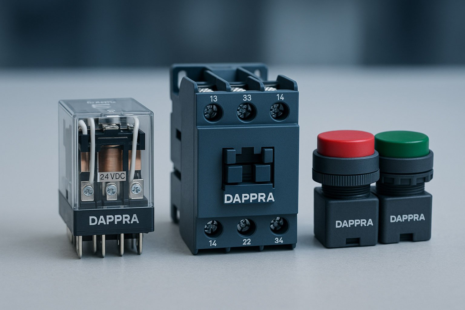
2. Relay Working Principles
A relay is a coil-driven switching device used for electrical and logical control.
2.1 Coil → Contact Operation
When voltage energizes the coil:
- Magnetic field forms
- Contacts change state
- NO turns ON, NC turns OFF
2.2 NO / NC Contact Logic
Relays usually include:
- NO (Normally Open) → activates when coil is energized
- NC (Normally Closed) → deactivates when coil is energized
These form the basis of ladder logic and safety interlocks.
2.3 Relay as the Foundation of Logic Control
Before PLC existed:
- Relays handled all logic
- Motor control circuits were built using relay sequences
Today, they are still essential for interface protection.
3. Contactor Structure
Contactors switch high-power loads (motors, heaters).
3.1 Main Contacts / Auxiliary Contacts
- Main contacts → handle motor power
- Auxiliary contacts (NO/NC) → used for interlocks & self-holding
3.2 Coil Voltage
Common coil voltages:
- AC 220V
- AC 110V
- DC 24V
- DC 12V
Correct voltage selection avoids coil overheating.
3.3 Arc Suppression System
When the contact opens:
- Arc forms
- Arc chute extinguishes arc
- Prevents burning or welding
4. Push Button Switch Structure
Push buttons are the simplest but most important human–machine interface.
4.1 NO / NC Buttons
- NO → start buttons, operation triggers
- NC → stop buttons, safety circuits
4.2 Momentary vs Latching
- Momentary (Self-reset) → returns when released
- Latching → stays locked (older designs, rarely used now)
4.3 Emergency Stop Button
Features include:
- Mushroom head
- Twist-release or key-release
- Always NC (fail-safe)
- Interrupts the control loop
5. Control Circuit Examples
5.1 Start–Stop Circuit
Consists of:
- Start NO button
- Stop NC button
- Contactor coil
- Auxiliary self-hold contact
5.2 Self-Latching Circuit
Used for motors:
Press Start → Coil energizes → AUX NO closes → Coil stays energized
Press Stop → AUX drops → Motor stops
5.3 Forward–Reverse Control Logic
Two contactors:
- K1 → Forward
- K2 → Reverse
Mutual interlock prevents short-circuit.
6. Common Engineering Problems
6.1 Relay Contact Arcing
Caused by:
- High load
- No suppression circuit
- Worn contacts
6.2 Contactor Unstable Pull-in
Causes:
- Low coil voltage
- Dirty core
- Mechanical wear
6.3 Push Button Poor Contact
Typical causes:
- Dust
- Oxidation
- Loose terminals
7. Best Practices
✔ Use Relays to Protect PLC Outputs
PLC should not directly drive contactor coils.
✔ Install Surge Absorbers (RC / Varistor)
Prevents coil back-EMF from damaging PLC/relays.
✔ Match Contact Rating with Load
Ensures long service life and prevents overheating.
✔ Regular Inspection & Tightening
Loose terminals cause 80% of failures.


Tambah komentar
Anda harus masuk untuk berkomentar.