Tidak ada produk di keranjang.

Kembali ke halaman sebelumnya
Industrial Area Sensor & Safety Light Curtain — DRM Series
DAPPRA Relay Safety Light Curtain
DRM Series — Relay
Safety Light Curtain
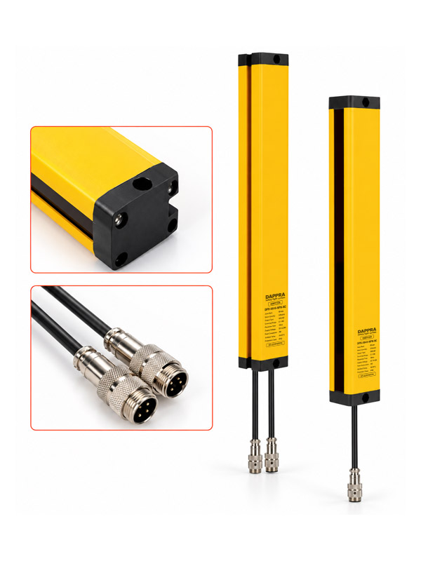
The DAPPRA DRM Series is a relay safety light curtain designed for machinery safety protection. It uses relay output and is widely used across automation equipment, small and medium-sized machinery.
The DRM Series uses a 30 × 35 mm aluminium alloy housing with an internal vibration-resistant structure, providing reliable detection in high-vibration environments. It supports 20 / 40 mm optical-axis pitch and relay output, with a standard detection distance of 0.1–3 m.
20 / 40 mm
Optical-Axis Pitch
≤5 ms
Relay Response Time
3 m
Standard Detection Distance
IP65
Protection Rating
Overview
DRM Series Overview
The DAPPRA DRM Series is a relay safety light curtain series primarily used for machinery safety protection. The product uses relay output, with a working voltage of 10–30 V DC and isolated relay contact output for direct switching of machine control circuits.
Internal components use imported original parts for stable performance. The vibration-resistant aluminium alloy housing and complete self-checking functions make the DRM Series suitable for pressing, cutting, extrusion and other vibration equipment.
The series provides 20 mm and 40 mm optical-axis pitch configurations, with beam quantities from 4 up to 256 and multiple protection heights and total heights for different industrial sensing and protection requirements. The standard detection distance is 0.1–3 m, and longer distances are available on request.
Key Features
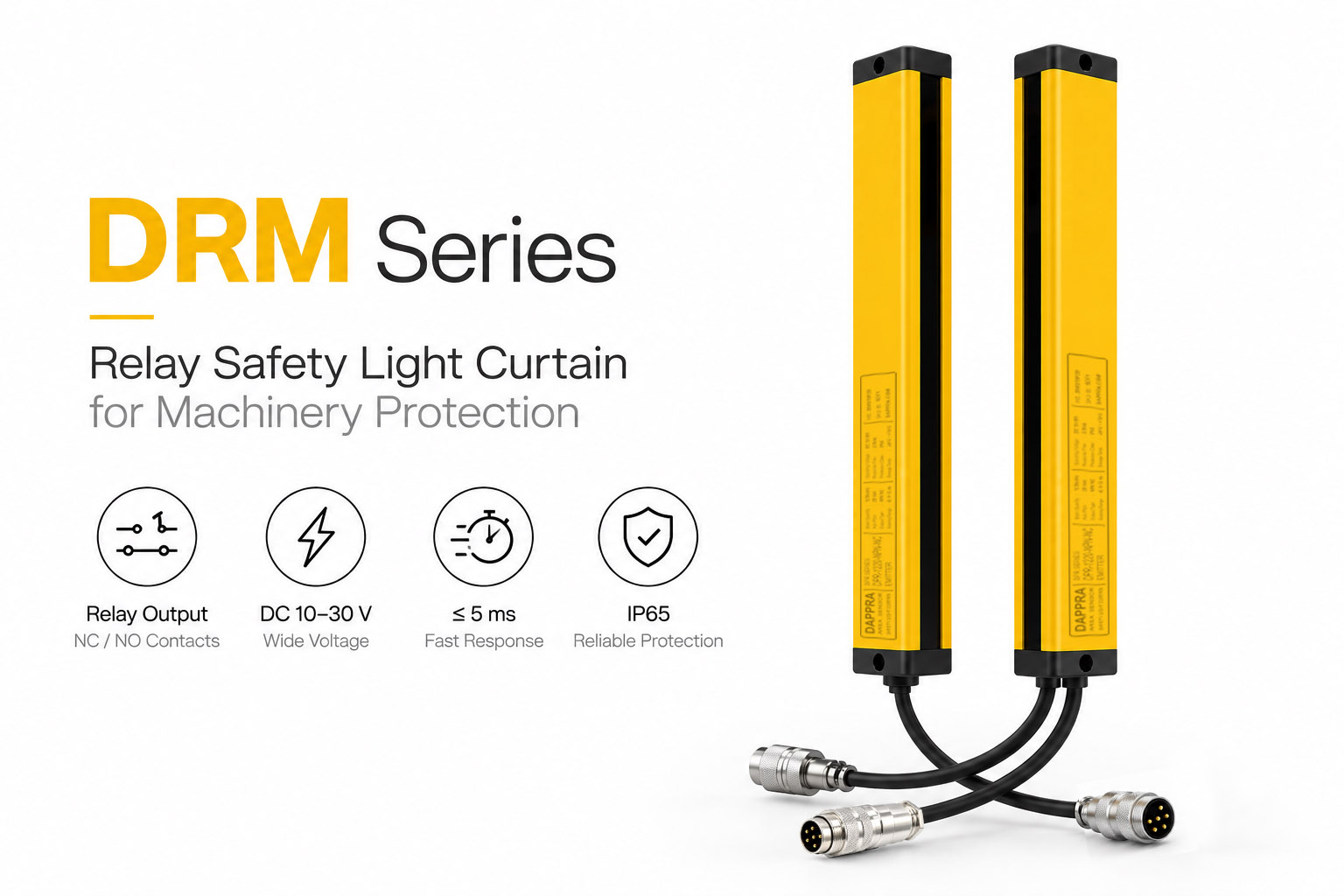
DRM Series Key Features
Engineered for machinery safety protection with relay output and a vibration-resistant structure.
-
Relay Output The DRM Series uses relay output with isolated common, normally-closed and normally-open contacts for direct switching of machine control circuits.
-
Wide Working Voltage Range Operates on DC 10–30 V, matching a wide range of industrial power environments.
-
Vibration-Resistant Structure Aluminium alloy housing with an internal vibration-resistant structure, suitable for pressing, cutting, extrusion and other vibration equipment.
-
20 / 40 mm Optical-Axis Pitch Two optical-axis pitch options provide different resolution and protection configurations for different machine sizes.
-
0.1–3 m Standard Detection Distance The DRM Series provides a standard protection distance of 0.1–3 m. Longer detection distances are available on request.
-
Fast Response Response time is ≤ 5 ms.
-
Line Synchronization The emitter and receiver use line synchronization for coordinated optical-beam operation and strong resistance to interference.
-
Complete Self-Checking Function Self-diagnostic function supports safe and stable operation in industrial environments.
-
Integrated Protection Circuitry Power supply over-voltage protection, reverse-polarity protection and output over-current protection are built in as standard.
-
Multiple Mounting Options Side mounting brackets are included as standard, with cantilever brackets available as options for different machine structures.
Model Selection
DRM Series Model Selection
Select the appropriate DRM model according to the optical-axis pitch, beam quantity and output type.
The DRM Series is available in 20 mm and 40 mm optical-axis pitch configurations, with beam quantities from 4 up to 256 and multiple protection heights and total heights for different industrial protection requirements.
Protection height (H) is calculated as (beam quantity − 1) × optical-axis pitch. Total height (L) additionally includes the upper and lower end caps and the PCB blind zones at each end of the light curtain.
Model Code
DRM
–
04
20
–
R
DRM
Series prefix — DAPPRA DRM Series Relay Safety Light Curtain.
04 — Beam Quantity
Number of optical beams, from 04 to 256 depending on the model.
20 — Optical-Axis Pitch
Optical-axis pitch in mm: 20 / 40.
R — Output Type
R = relay output. The DRM Series uses relay output as standard.
Field
Meaning
Available Values
DRM
Series prefix
DRM
Beam Quantity
Number of optical beams
04 – 256
Optical-Axis Pitch
Distance between adjacent optical axes
20 / 40 mm
Output Type
Relay output
R
Example: DRM-0420-R = DRM Series, 4 beams, 20 mm optical-axis pitch, relay output.
Optical Axis Pitch D = 20 mm | Resolution 20 mm
| Beam Quantity | Protection Height (H) mm | Total Height (L) mm | Model |
|---|---|---|---|
| 4 | 60 | 120 | DRM-0420-R |
| 6 | 100 | 160 | DRM-0620-R |
| 8 | 140 | 200 | DRM-0820-R |
| 10 | 180 | 240 | DRM-1020-R |
| 12 | 220 | 280 | DRM-1220-R |
| 14 | 260 | 320 | DRM-1420-R |
| 16 | 300 | 360 | DRM-1620-R |
| 18 | 340 | 400 | DRM-1820-R |
| 20 | 380 | 440 | DRM-2020-R |
| 22 | 420 | 480 | DRM-2220-R |
| 24 | 460 | 520 | DRM-2420-R |
| 26 | 500 | 560 | DRM-2620-R |
| 28 | 540 | 600 | DRM-2820-R |
| 30 | 580 | 640 | DRM-3020-R |
| 32 | 620 | 680 | DRM-3220-R |
| · · · Intermediate beam quantities available up to 256 · · · | |||
20 mm optical-axis pitch models are available with beam quantities from 4 to 256. Protection height H = (Beam Quantity − 1) × 20 mm. Total height L = Top cap + Bottom cap + Blind zones + Protection height.
Optical Axis Pitch D = 40 mm | Resolution 40 mm
| Beam Quantity | Protection Height (H) mm | Total Height (L) mm | Model |
|---|---|---|---|
| 4 | 120 | 192 | DRM-0440-R |
| 6 | 200 | 272 | DRM-0640-R |
| 8 | 280 | 352 | DRM-0840-R |
| 10 | 360 | 432 | DRM-1040-R |
| 12 | 440 | 512 | DRM-1240-R |
| 14 | 520 | 592 | DRM-1440-R |
| 16 | 600 | 672 | DRM-1640-R |
| 18 | 680 | 752 | DRM-1840-R |
| 20 | 760 | 832 | DRM-2040-R |
| 22 | 840 | 912 | DRM-2240-R |
| 24 | 920 | 992 | DRM-2440-R |
| 26 | 1000 | 1072 | DRM-2640-R |
| 28 | 1080 | 1152 | DRM-2840-R |
| 30 | 1160 | 1232 | DRM-3040-R |
| 32 | 1240 | 1312 | DRM-3240-R |
| · · · Intermediate beam quantities available up to 256 · · · | |||
40 mm optical-axis pitch models are available with beam quantities from 4 to 256. Protection height H = (Beam Quantity − 1) × 40 mm. Total height L = Top cap + Bottom cap + Blind zones + Protection height.
Protection heights outside the listed standard range can be customized. All dimensions are manually measured and are for reference only — please refer to the actual product for final dimensions.
Technical Parameters
DRM Series Technical Specifications
Confirmed electrical, optical and environmental parameters for the DAPPRA DRM Series.
| Protection Height | 60 – 2000 mm (standard); custom heights available |
| Optical-Axis Pitch | 20 / 40 mm |
| Resolution | 20 / 40 mm |
| Beam Quantity | 20 mm pitch: 4 – 256 · 40 mm pitch: 4 – 256 |
| Detection Distance | 0.1 – 3 m (standard) |
| Response Time | ≤ 5 ms |
| Operating Voltage | DC 10 – 30 V |
| Output Current | ≤ 200 mA |
| Power Consumption | < 5 W |
| Output Type | Relay output (common / normally-closed / normally-open contacts) |
| Synchronization | Line synchronization |
| Protection Circuitry | Power over-voltage protection, reverse-polarity protection, output over-current protection |
| Insulation Resistance | ≥ 100 MΩ |
| Dielectric Strength | AC 1500 V, 60 s — no breakdown or flashover |
| Housing Cross Section | 30 × 35 mm |
| Housing Material | Aluminium alloy |
| Protection Rating | IP65 |
| Operating Temperature | −10 ~ 55 °C |
| Operating Humidity | < 85 % RH at 20 °C |
| Light Interference Resistance | 10,000 Lux (incident angle > 5°) |
Dimensions
DRM Series Dimensions
The DRM Series uses a 30 × 35 mm aluminium alloy housing with an internal vibration-resistant structure, designed for machinery safety protection and vibration-heavy equipment.
Protection height is determined by the beam quantity and optical-axis pitch of each model. Total height additionally includes the upper and lower end caps and the PCB blind zones at each end of the light curtain.
For complete mechanical dimensions, refer to the corresponding DRM model page and CAD drawing.
| Housing Cross Section | 30 × 35 mm |
| Upper End Cap (A1) | 10 mm |
| Lower End Cap (A2) | 10 mm |
| PCB Upper Blind Zone (B1) | 13 mm (D = 20 mm) / 7 mm (D = 40 mm) |
| PCB Lower Blind Zone (B2) | 27 mm (D = 20 mm) / 45 mm (D = 40 mm) |
| Optical-Axis Pitch (D) | 20 / 40 mm |
| Protection Height (H) | (Beam Quantity − 1) × Optical-Axis Pitch |
| Total Height (L) | A1 + A2 + B1 + B2 + H |
| Mounting | Side mounting / cantilever |
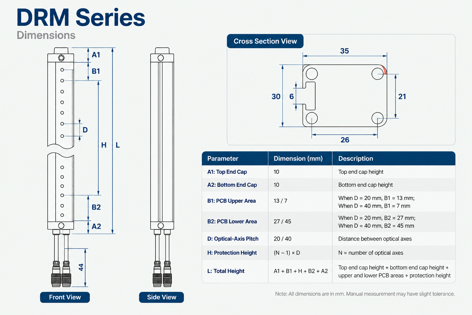
Measurement unit: mm. Data is manually measured and may contain minor deviations — please refer to the actual product for final dimensions.
Installation & Mounting
DRM Series Installation & Mounting Options
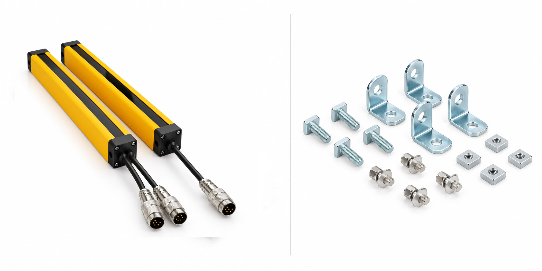
The DRM Series supports multiple mounting configurations for different machinery structures. Side mounting brackets are included as standard, with cantilever brackets available as options.
Standard
Side Mounting Brackets
Standard side mounting brackets with side-fixing brackets, M5 square-head long screws, M5 round-head long screws and square sliding blocks for conventional installation.
Optional
Cantilever Brackets
Cantilever mounting support with rotary arm, cantilever support rod, standard sliding blocks and M5 / M6 / M18 screws for extended mounting positions.
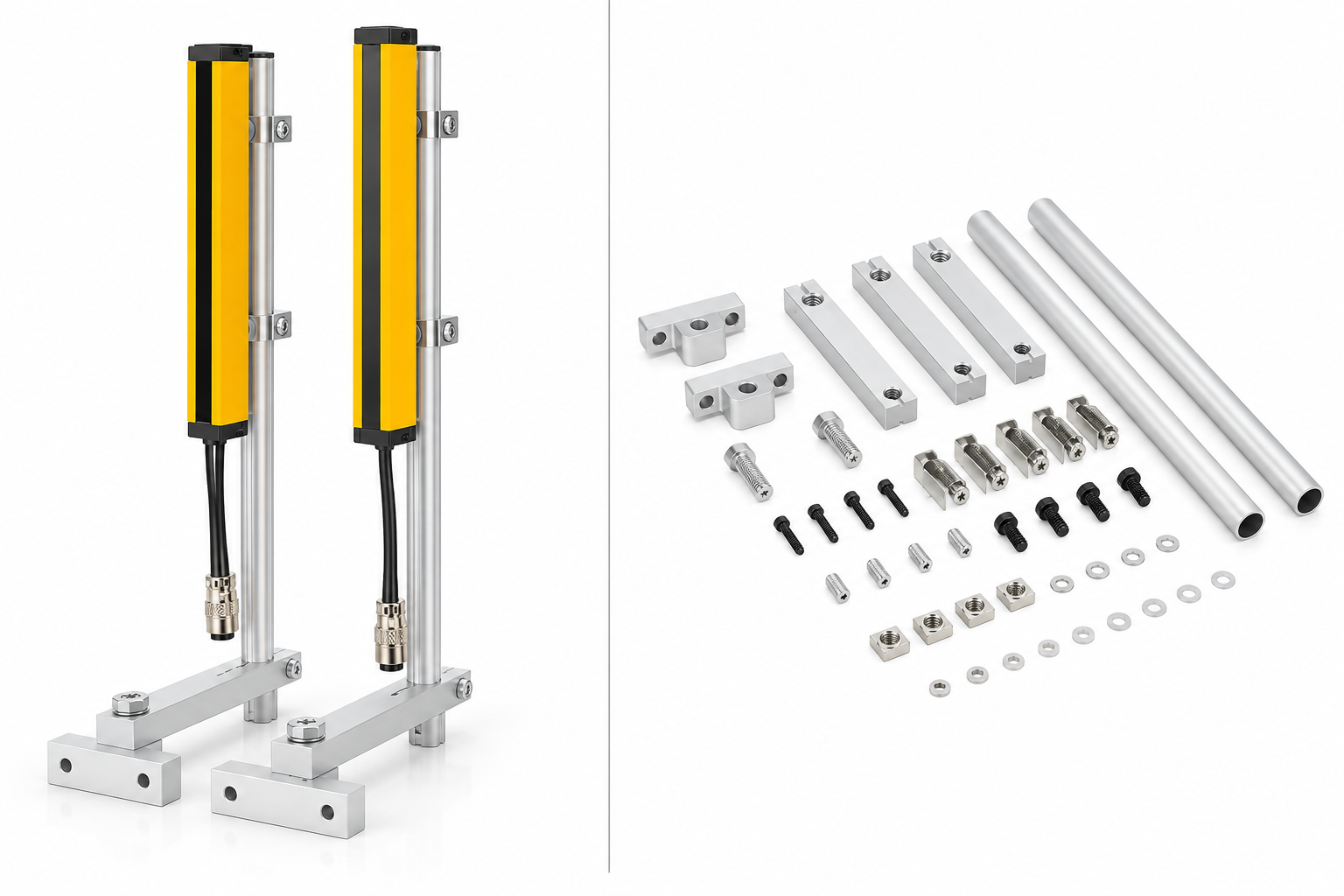
The appropriate mounting configuration should be selected according to the machine structure and available installation space.
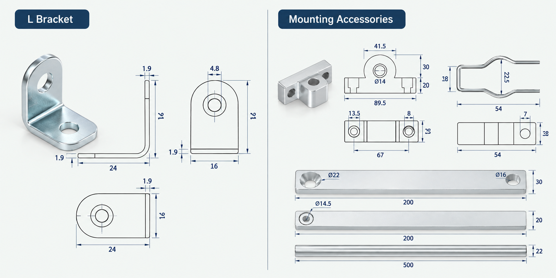
Wiring Principle
DRM Series Wiring Principle
The DRM Series uses relay output at 10–30 V DC. The receiver provides a sync port and a 5-wire output port for connection to the machine control circuit.
Relay Output Wiring
The relay output provides isolated common, normally-closed and normally-open contacts for direct switching of machine control circuits. Connect the receiver relay contacts in series with the machine stop circuit or safety relay according to the wiring diagram below.
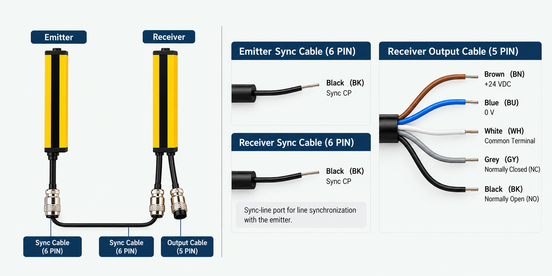
Emitter / Receiver Wire Colour Reference
Emitter
  Sync CP  ····································  Black  (BK)
  (Emitter has a single sync-line port only. This sync cable is a 6-core cable.)

Receiver — Port 1
  Sync CP  ····································  Black  (BK)
  (Sync-line port for line synchronization with the emitter. This sync cable is a 6-core cable.)

Receiver — Port 2 (5-wire output port)
  +24 VDC  ···································  Brown  (BN)
  0 V      ···································  Blue   (BU)
  Common Terminal  ···························  White  (WH)
  Normally Closed  ···························  Grey   (GY)
  Normally Open  ····························  Black  (BK)
The actual wiring should follow the wiring diagram provided for the selected DRM model. The DRM Series uses relay output only — verify the relay contact wiring (common / normally-closed / normally-open) before connecting to the machine control circuit.
Accessories
DRM Series Accessories
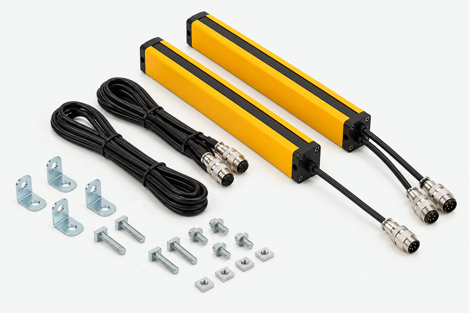
The DRM Series includes the emitter and receiver as the main sensing components. Signal cables, mounting brackets and documentation are provided for installation and system connection.
01 / 04
Safety Light Curtain × 2
Emitter and receiver pair — the main sensing components of the DRM Series.
02 / 04
Signal Connection Cable × 2
Approximately 3 m cable length as standard; custom cable lengths available.
03 / 04
Side Mounting Bracket Set × 1
Standard side mounting bracket set. Cantilever brackets are available as options.
04 / 04
User Manual × 1
Includes wiring instructions, installation instructions and operating instructions.
The exact accessory configuration may vary according to the selected DRM model and mounting requirements.
Applications
DRM Series Industrial Applications
The DRM Series is suitable for machinery safety protection, automation equipment, small and medium-sized machinery, pressing equipment, cutting equipment, extrusion equipment and other vibration-heavy industrial equipment.
Machine Protection
Personnel Protection
Pressing Equipment
Cutting Equipment
Extrusion Equipment
Automation Equipment
Small & Medium Machinery
Hydraulic Machinery
Robotic Equipment
Assembly Stations
Material Detection
Machine Area Detection
Next Step
Explore the DRM Series
Browse all DRM Series relay safety light curtain products, or return to the Industrial Area Sensor & Safety Light Curtain category page.
Support
DRM Series FAQ
What is the DAPPRA DRM Series?
The DAPPRA DRM Series is a relay safety light curtain series for machinery safety protection. It uses relay output, a 30 × 35 mm aluminium alloy housing with an internal vibration-resistant structure, and is suitable for pressing, cutting and extrusion equipment.
Which optical-axis pitches are available in the DRM Series?
The DRM Series provides 20 mm and 40 mm optical-axis pitch configurations.
What is the housing cross section of the DRM Series?
The DRM Series uses a 30 × 35 mm aluminium alloy housing with an internal vibration-resistant structure.
What is the response time of the DRM Series?
The DRM Series response time is ≤ 5 ms.
What is the standard detection distance of the DRM Series?
The DRM Series supports a standard protection distance of 0.1–3 m. Longer detection distances are available on request.
What output type does the DRM Series use?
The DRM Series uses relay output. The model code letter R indicates relay output.
What relay contact types are available on the DRM receiver?
The DRM receiver provides a common terminal, a normally-closed contact and a normally-open contact for direct switching of machine control circuits.
What is the protection rating of the DRM Series?
The DRM Series uses an aluminium alloy housing with an IP65 protection rating.
What is the operating voltage of the DRM Series?
The DRM Series operates on DC 10–30 V, with an output current of ≤ 200 mA and a power consumption of less than 5 W.