Tidak ada produk di keranjang.

Kembali ke halaman sebelumnya
Industrial DIN Rail Power Supply – SDR Series
DAPPRA DIN Rail Industrial Power Supply
SDR Series — High-Efficiency
DIN Rail Power Supply with PFC
The DAPPRA SDR Series is a high-efficiency single-output DIN rail power supply series with built-in active PFC, designed for industrial control and automation systems requiring high peak load capability.
Covering 75W to 960W with 12V to 48V output, the SDR Series combines high efficiency up to 94%, 150% peak load capability (130% on SDR-960), built-in DC OK relay contact and SEMI F47 compliance. The SDR-480P and SDR-960 support parallel current sharing up to 3840W.

75–960 W
Output Power
up to 94%
Efficiency
150%
Peak Load (3 sec)
3840 W
Max Current Sharing
Overview
SDR Series Overview
The DAPPRA SDR Series is a high-efficiency single-output DIN rail power supply series with built-in active PFC, designed for industrial control and automation systems. It covers five power ratings — 75W, 120W, 240W, 480W and 960W — with single-output configurations of 12V, 24V and 48V DC.
The series features high efficiency up to 94%, 150% peak load capability for 3 seconds (130% on SDR-960), built-in DC OK relay contact and complete protection functions including short circuit, overload, over voltage and over temperature protection. The SDR-480P and SDR-960 support parallel current sharing up to 3840W, and all models are compliant with SEMI F47 and BS EN/EN61000-6-2 industrial immunity level.
Key Features
SDR Series Key Features
Engineered for high-efficiency, high peak-load industrial power supply applications.
- High Efficiency up to 94%Efficiency ranges from 88.5% (SDR-75-12) up to 94% (SDR-240, SDR-480 and SDR-960 models), reducing energy consumption and heat generation inside control cabinets.
- 150% Peak Load Capability (3 seconds)SDR-75, SDR-120, SDR-240, SDR-480 and SDR-480P deliver 150% peak power for 3 seconds to support inductive and capacitive loads during startup. SDR-960 offers 130% peak load capability.
- Built-in Active PFC FunctionSDR-120, SDR-240, SDR-480, SDR-480P and SDR-960 feature built-in active PFC with PF >0.93 under full load, compliant with BS EN/EN61000-3-2 harmonic current regulations.
- Parallel Current Sharing (480P / 960)SDR-480P supports current sharing up to 3840W (7+1 parallel units). SDR-960 supports current sharing up to 3840W (3+1 parallel units). Both models support parallel operation for high-power or redundant applications.
- Built-in DC OK Relay ContactAll SDR models include a built-in DC OK relay contact for remote status monitoring. Contact Close = PSU turns on / DC OK. Contact Open = PSU turns off / DC Fail.
- Complete Protection FunctionsShort circuit protection, overload protection (constant current limiting with auto-recovery), over voltage protection and over temperature protection are built in.
- Slim Metal HousingSDR-75 and SDR-120 are 32 mm and 40 mm wide; SDR-240 is 63 mm; SDR-480 and SDR-480P are 85.5 mm; SDR-960 is 110 mm. Metal housing enhances heat dissipation and provides mechanical robustness.
- SEMI F47 CompliantAll models are approved for SEMI F47, suitable for semiconductor fabrication equipment and other applications requiring high immunity to voltage sags.
- TS35 DIN Rail MountingAdmissible DIN rail: TS35/7.5 or TS35/15. UL508 approved. 3 years warranty.
Model Selection
SDR Series Model Selection
Select the appropriate SDR model according to the required output power, output voltage and current sharing requirement.
The SDR Series is available in five power ratings — 75W, 120W, 240W, 480W and 960W — with an additional SDR-480P model that includes parallel current sharing. SDR-75 and SDR-120 offer 12V, 24V and 48V; SDR-240, SDR-480, SDR-480P and SDR-960 offer 24V and 48V.
Model Code
SDR
–
480
P
–
24
SDRSeries prefix — DAPPRA SDR Series High-Efficiency DIN Rail Power Supply with PFC.
480 — Output WattageOutput power rating in Watts: 75 / 120 / 240 / 480 / 960.
P — Parallel Function (Optional)Indicates current sharing / parallel operation capability (SDR-480P only).
24 — Output VoltageNominal output voltage in VDC: 12 / 24 / 48 (varies by power rating).
Field
Meaning
Available Values
SDR
Series prefix
SDR
Output Wattage
Rated output power in Watts
75 / 120 / 240 / 480 / 960
Parallel Suffix
Current sharing / parallel operation
Blank / P (parallel, 480W only)
Output Voltage
Nominal DC output voltage
12 / 24 / 48 VDC
Example: SDR-480P-24 = SDR Series, 480W output power, parallel function, 24V DC output.
SDR-75 — 75W
| Model | Output Voltage | Output Current | Rated Power | Peak Power (3 sec.) | Efficiency | Width |
|---|---|---|---|---|---|---|
| SDR-75-12 | 12 VDC | 6.3 A | 75.6 W | 112.5 W | 88.5% | 32 mm |
| SDR-75-24 | 24 VDC | 3.2 A | 76.8 W | 112.5 W | 89% | 32 mm |
| SDR-75-48 | 48 VDC | 1.6 A | 76.8 W | 112.5 W | 90% | 32 mm |
SDR-120 — 120W with PFC
| Model | Output Voltage | Output Current | Rated Power | Peak Power (3 sec.) | Efficiency | Width |
|---|---|---|---|---|---|---|
| SDR-120-12 | 12 VDC | 10 A | 120 W | 180 W | 89% | 40 mm |
| SDR-120-24 | 24 VDC | 5 A | 120 W | 180 W | 91% | 40 mm |
| SDR-120-48 | 48 VDC | 2.5 A | 120 W | 180 W | 90.5% | 40 mm |
SDR-240 — 240W with PFC
| Model | Output Voltage | Output Current | Rated Power | Peak Power (3 sec.) | Efficiency | Width |
|---|---|---|---|---|---|---|
| SDR-240-24 | 24 VDC | 10 A | 240 W | 360 W | 94% | 63 mm |
| SDR-240-48 | 48 VDC | 5 A | 240 W | 360 W | 94% | 63 mm |
SDR-480 / SDR-480P — 480W with PFC (and Parallel)
| Model | Output Voltage | Output Current | Rated Power | Peak Power (3 sec.) | Efficiency | Parallel Function |
|---|---|---|---|---|---|---|
| SDR-480-24 | 24 VDC | 20 A | 480 W | 720 W | 94% | No |
| SDR-480-48 | 48 VDC | 10 A | 480 W | 720 W | 94% | No |
| SDR-480P-24 | 24 VDC | 20 A | 480 W | 720 W | 94% | Yes (7+1, up to 3840W) |
| SDR-480P-48 | 48 VDC | 10 A | 480 W | 720 W | 94% | Yes (7+1, up to 3840W) |
SDR-960 — 960W with PFC (and Parallel)
| Model | Output Voltage | Output Current | Rated Power | Peak Power (3 sec.) | Efficiency | Input Voltage |
|---|---|---|---|---|---|---|
| SDR-960-24 | 24 VDC | 40 A | 960 W | 1248 W (130%) | 94% | 180–264 VAC only |
| SDR-960-48 | 48 VDC | 20 A | 960 W | 1248 W (130%) | 94% | 180–264 VAC only |
SDR-960 supports current sharing up to 3840W (3+1 parallel units). The input voltage is restricted to 180–264 VAC only.
Dimensions
SDR Series Dimensions
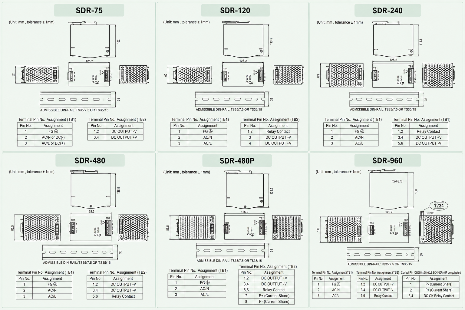
Slim metal housing with a compact footprint designed for space-constrained control cabinets. All dimensions in mm, tolerance ±1 mm.
SDR-75
| Width (W) | 32 mm |
| Height (H) | 125.2 mm |
| Depth (D) | 102 mm |
| Housing | Metal, slim design |
| Front Panel | +V ADJ / DC OK |
SDR-120
| Width (W) | 40 mm |
| Height (H) | 125.2 mm |
| Depth (D) | 113.5 mm |
| Housing | Metal, slim design |
| Front Panel | +V ADJ / DC OK |
SDR-240
| Width (W) | 63 mm |
| Height (H) | 125.2 mm |
| Depth (D) | 113.5 mm |
| Housing | Metal, slim design |
| Front Panel | +V ADJ / DC OK |
SDR-480 / SDR-480P
| Width (W) | 85.5 mm |
| Height (H) | 125.2 mm |
| Depth (D) | 128.5 mm |
| Housing | Metal, slim design |
| Front Panel | +V ADJ / DC OK |
SDR-960
| Width (W) | 110 mm |
| Height (H) | 125.2 mm |
| Depth (D) | 150 mm |
| Housing | Metal, slim design |
| Front Panel | +V ADJ / DC OK |
Mounting
| DIN Rail | TS35/7.5 or TS35/15 |
| Cooling | Free air convection (fanless) |
| Orientation | Vertical (input at bottom) |
| Operating Temp. | SDR-75: -30~+70°C; others: -25~+70°C |
Installation
SDR Series Installation
The SDR Series supports DIN rail mounting with specific ventilation clearance and orientation requirements for reliable operation.
01 / 06
Vertical Orientation Only
The appropriate mounting orientation is vertical — input terminals at the bottom and output terminals at the top. Upside-down, horizontal or table-top mounting is not allowed, as sufficient cooling will not be possible.
02 / 06
Ventilation Clearance
Always allow good ventilation clearances around the unit: 5 mm left and right, 40 mm above and 20 mm below, to prevent overheating. When the adjacent device is a heat source, keep 15 mm clearance.
03 / 06
TS35 DIN Rail Mounting
Admissible DIN rail: TS35/7.5 or TS35/15. Tilt the unit slightly rearwards, fit over the top hat rail, slide it downward until it hits the stop, press against the bottom for locking, then shake slightly to check the locking action.
04 / 06
FG Must Be Connected to PE
The FG (Frame Ground) terminal must be connected to PE (Protective Earth) for safety and to ensure proper EMC performance.
05 / 06
Operating Temperature Limits
SDR-75: -30 to +70°C (derating above +60°C). SDR-120/240/480/480P/960: -25 to +70°C (derating above +50°C or +60°C). Do not install near fire sources or high ambient temperature locations.
06 / 06
Pollution Degree 2 Environment
Install the unit only in a pollution degree 2 environment — typically dry, well-ventilated locations such as control cabinets. Do not install in places with high moisture or near water.
The SDR Series operates with free air convection cooling and requires adequate ventilation clearance. Do not install in orientations other than vertical, such as upside down, horizontal or table-top mounting.
Wiring & Terminal
SDR Series Wiring & Terminal
TB1 input terminal is consistent across all models. TB2 output terminal pin order varies by model — verify the terminal label before wiring.
Terminal Pin Assignment
TB1 — Input Terminal (All Models)
| Pin No. | Assignment |
|---|---|
| 1 | FG (Frame Ground) |
| 2 | AC/N |
| 3 | AC/L |
All SDR models use the same TB1 input terminal. FG must be connected to PE.
TB2 — Output Terminal (SDR-75) — 4 Pins
| Pin No. | Assignment |
|---|---|
| 1, 2 | DC OUTPUT -V |
| 3, 4 | DC OUTPUT +V |
SDR-75 TB2 has no relay contact terminal.
TB2 — Output Terminal (SDR-120) — 4 Pins
| Pin No. | Assignment |
|---|---|
| 1, 2 | DC OK relay contact |
| 3 | DC OUTPUT -V |
| 4 | DC OUTPUT +V |
TB2 — Output Terminal (SDR-240) — 6 Pins
| Pin No. | Assignment |
|---|---|
| 1, 2 | DC OK relay contact |
| 3, 4 | DC OUTPUT +V |
| 5, 6 | DC OUTPUT -V |
TB2 — Output Terminal (SDR-480) — 6 Pins
| Pin No. | Assignment |
|---|---|
| 1, 2 | DC OUTPUT +V |
| 3, 4 | DC OUTPUT -V |
| 5, 6 | DC OK relay contact |
SDR-480 TB2 order differs from SDR-240 — +V is first.
TB2 — Output Terminal (SDR-480P) — 8 Pins
| Pin No. | Assignment |
|---|---|
| 1, 2 | DC OUTPUT +V |
| 3, 4 | DC OUTPUT -V |
| 5, 6 | DC OK relay contact |
| 7 | P+ (current share) |
| 8 | P- (current share) |
SDR-480P adds 2 pins (7, 8) for parallel current sharing.
TB2 — Output Terminal (SDR-960) — 6 Pins
| Pin No. | Assignment |
|---|---|
| 1, 2, 3 | DC OUTPUT +V |
| 4, 5, 6 | DC OUTPUT -V |
SDR-960 TB2 uses 3 pins per polarity. Current sharing and DC OK are on a separate CN205 connector.
CN205 — Control Pin (SDR-960 Only)
| Pin No. | Assignment |
|---|---|
| 1 | P- (current share) |
| 2 | P+ (current share) |
| 3, 4 | DC OK relay contact |
Mating housing: DINKLE ESC250V-04P or equivalent. Wire diameter: 0.081–0.517 mm² (28–20 AWG).
TB2 pin order varies between SDR-75, SDR-120, SDR-240, SDR-480, SDR-480P and SDR-960 — always verify the terminal label before wiring. Both -V pins and both +V pins should be connected to their respective output wires to prevent excessive current stress on a single contact. The FG pin must be connected to PE (Protective Earth).
DC OK Relay Contact
DC OK Contact State
| State | Condition |
|---|---|
| Contact Close | PSU turns on / DC OK |
| Contact Open | PSU turns off / DC Fail |
| Max Rating (all models) | 30V / 1A resistive load |
| Max Rating (SDR-480P / 960) | 60VDC/0.3A, 30VDC/1A, 30VAC/0.5A |
Wiring Specification
| Model Group | Torque |
|---|---|
| SDR-75 / 120 | 5 kgf-cm (4.4 Lb-in) |
| SDR-240 / 480 / 480P | 10 kgf-cm (9 Lb-in) |
| SDR-960 | 10 kgf-cm (9 Lb-in) |
Use stranded copper wire only. Recommended wire strapping length: 5 mm (0.197″). Recommended screwdriver: 3 mm or 4 mm slotted type.
DC Output Voltage Adjustment
All SDR models include a front-panel DC output voltage adjustment potentiometer (+V ADJ) and a DC OK indicator LED. The rated output voltage can be adjusted within the voltage adjustment range specified for each model. Output current and output wattage must not exceed the rated value on its specification.
The actual wiring should follow the wiring diagram provided in the SDR Series installation manual. Use copper wire only and ensure all strands enter the terminal connection securely.
Safety & Compliance
SDR Series Safety & Cautions
Read and follow all safety instructions before installing, wiring, maintaining or modifying the SDR Series power supply.
- Risk of electrical shock and energy hazard. All failure should be examined by a qualified technician. Do not remove the case of the power supply yourself.
- Connecting both the primary and the secondary sides together is not allowed — risk of electric arcs and electric shock (danger to life).
- Risk of burn hazard. Do not touch the unit in operation and shortly after disconnection.
- Risk of fire and short circuit. The openings should be protected from foreign objects or dripping liquids.
- The FG (Frame Ground) must be connected to PE (Protective Earth).
- Output current and output wattage must not exceed the rated value on its specification.
- Before commencing any installation, maintenance or modification work, disconnect the system from supply voltage. Make sure that inadvertent connection in circuit will be impossible.
- For continued protection against risk of fire, replace only with the same type and rating of fuse.
- The power supply is considered a component which will be installed into a final equipment. The final equipment must be re-confirmed that it still meets EMC directives.
Note: Pollution Degree 2 applies where there is only non-conductive pollution that might temporarily become conductive due to occasional condensation. Generally refers to dry, well-ventilated locations, such as control cabinets.
Applications
SDR Series Industrial Applications
The SDR Series is suitable for industrial control systems, semiconductor fabrication equipment, factory automation and electromechanical apparatus.
Industrial Control Systems
Semiconductor Fabrication
Factory Automation
Electromechanical Apparatus
Electrical Panels
Process Control
Test & Measurement
Machine Control
Redundant Power Systems
Next Step
Explore the SDR Series
Browse all SDR Series DIN rail power supply products, or return to the Industrial Power Supply category page.
Support
SDR Series FAQ
What is the DAPPRA SDR Series?
The DAPPRA SDR Series is a high-efficiency single-output industrial DIN rail power supply series with built-in active PFC. It covers 75W, 120W, 240W, 480W and 960W power ratings with 12V, 24V and 48V output configurations.
What is the input voltage range of the SDR Series?
Most SDR Series models support a universal AC input range of 88–264 VAC or 124–370 VDC. The SDR-960 supports 180–264 VAC or 254–370 VDC only.
What output voltages are available in the SDR Series?
The SDR-75 and SDR-120 offer 12V, 24V and 48V output options. The SDR-240, SDR-480, SDR-480P and SDR-960 offer 24V and 48V output options.
Which SDR models have built-in active PFC?
The SDR-120, SDR-240, SDR-480, SDR-480P and SDR-960 models have built-in active PFC function with PF greater than 0.93 under full load, compliant with BS EN/EN61000-3-2.
What is the peak load capability of the SDR Series?
SDR-75, SDR-120, SDR-240, SDR-480 and SDR-480P offer 150% peak load capability for 3 seconds. The SDR-960 offers 130% peak load capability for 3 seconds.
Which SDR models support parallel current sharing?
The SDR-480P supports current sharing up to 3840W (7+1 parallel units). The SDR-960 supports current sharing up to 3840W (3+1 parallel units). Other SDR models do not support current sharing.
What is the efficiency of the SDR Series?
Efficiency ranges from 88.5% (SDR-75-12) up to 94% (SDR-240, SDR-480 and SDR-960 models), depending on the model and output voltage.
What is the terminal pin assignment of the SDR Series?
TB1 is consistent across all models: Pin 1 = FG, Pin 2 = AC/N, Pin 3 = AC/L. TB2 pin order varies by model: SDR-75 TB2: 1,2 = -V, 3,4 = +V. SDR-120 TB2: 1,2 = Relay Contact, 3 = -V, 4 = +V. SDR-240 TB2: 1,2 = Relay Contact, 3,4 = +V, 5,6 = -V. SDR-480 and SDR-480P TB2: 1,2 = +V, 3,4 = -V, 5,6 = Relay Contact (SDR-480P adds 7 = P+, 8 = P- for current sharing). SDR-960 TB2: 1,2,3 = +V, 4,5,6 = -V; CN205: 1 = P-, 2 = P+, 3,4 = DC OK Relay Contact.
What is the operating temperature range of the SDR Series?
SDR-75 operates from -30°C to +70°C. SDR-120, SDR-240, SDR-480, SDR-480P and SDR-960 operate from -25°C to +70°C. All models require derating above +50°C or +60°C depending on the model.
What certifications does the SDR Series have?
The SDR Series is certified to UL508, TUV BS EN/EN62368-1, AS/NZS 62368.1, EAC TP TC 004 and BSMI CNS15598-1. All models comply with BS EN/EN61000-6-2 industrial immunity level and are approved for SEMI F47.
How do I choose the right SDR Series model?
Select the SDR model according to the required output power (75W to 960W), output voltage, whether parallel current sharing is needed, and available DIN rail mounting space.